33
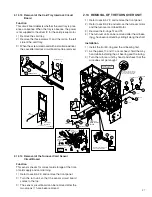
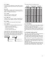
2.17 Thermal Head Exchange Method
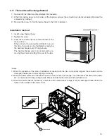
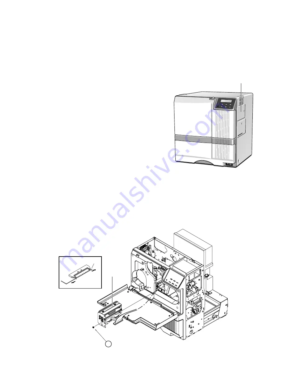
1) Remove the ink ribbon and the retranster film cassette.
2) When the locking claws on both sides of the head are spread, the connector can be disconnected. Remove the
connector by pulling it.
3) Remove the screw
!
. Pull the thermal head to the front to remove it.
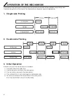
Installation method
1) Install a new thermal head.
2) Tighten the screw.
3) Press the connector near its center and insert it. The
claws will lock.
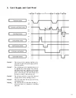
When a part of the connector is difficult to see at
this time, the work can be facilitated by removing
the head exchange cover of the enclosure.
The head exchange cover can be removed by re-
moving the screw and sliding the cover to the rear.
*Notes:
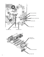
1) When the connector at the time of installation is inserted with the pins not correctly aligned, the connector will be
damaged. Please insert it after aligning it correctly.
2) When the heater element on the thermal head is hit at the time of exchange, it can become scratched white streaks
etc. can be caused for the printing results. Please handle the thermal head with sufficient care.
3) When the thermal head is touched by someone with an electrostatic charge, it may be damaged. Please touch the
frame of the unit before the start of work.
Head exchange cover
11
Locking claw
Thermal head
QYSDSP4008N

