37
2. Explanation of the Various Modes
2.1 Download
When changing the version of firmware inside the printer,
FPGA table or FPGA firmware, refer to the “XID580i main-
tenance CD-ROM” distributed separately.
2.2 Maintenance
2.2.1 Offset Prt Y Setting
For example, when printing with this printer is to be done
on preprinted cards and the position relation is not cor-
rect, the entire screen can be shifted.
The print position can be varied using the four items listed
below.
Changing any of the following items varies the print posi-
tion. However, do not touch the Card X because this is the
standard for the X-direction.
Use items (3) and (4) for fine adjustments.
* Items for varying the print position in the latitudinal
direction of the card:
(1) 2.2.4, Offset Card X: Adjusts the card feed amount
from the card edge sensor.
(2) 2.2.2, Offset Print X: Adjusts the feed amount from
the black marker to the start of printing.
(3) 2.2.3, Offset Trf X: Adjusts the feed amount to the
start of a retransfer.
* Item varying the print position in the longitudinal di-
rection of the card:
(4) 2.2.1, Offset Print Y: Adjusts the start position among
the 1152 head heater elements.
(1) Determines the displacement amount according to the
print results (those owned by the user). Every step
corresponds to a displacement of about 0.17 mm. The
step can be varied in the range between -15 and +15.
(2) Press ENTER to save the setting.
(3) Print and check the result.
(4) To adjust to the standard setting:
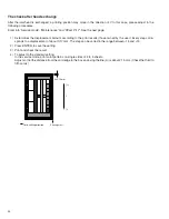
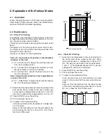
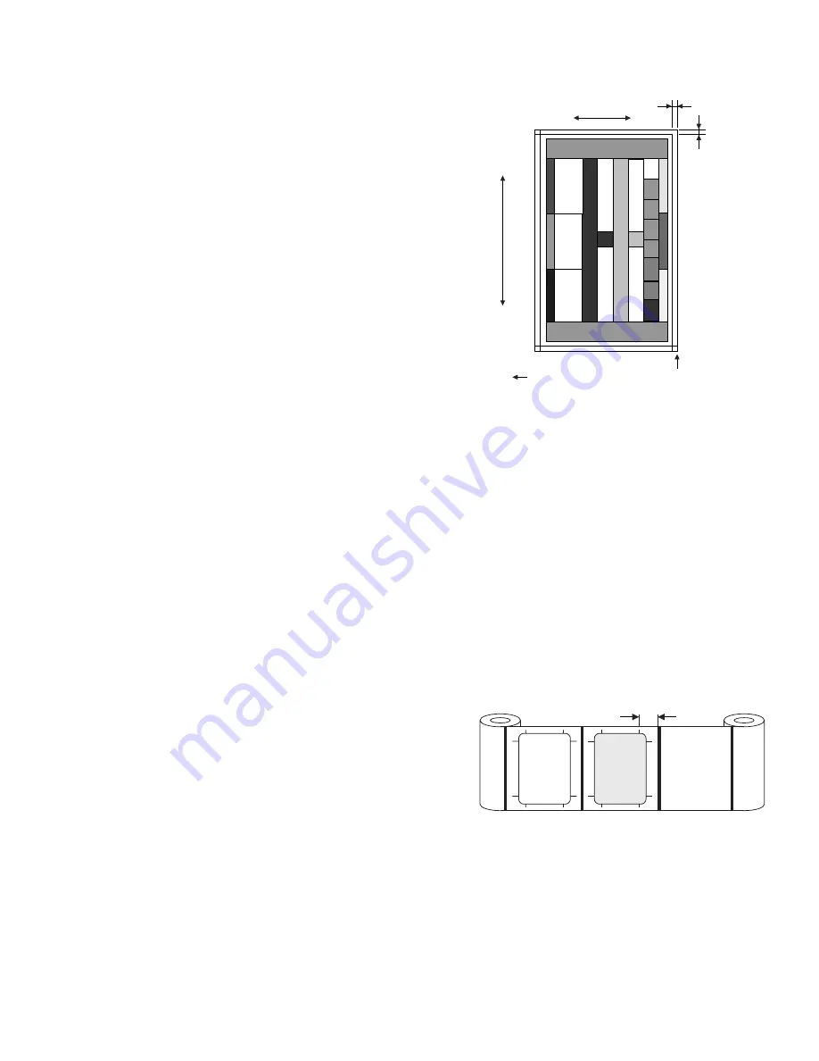
In the service mode, print color patterns on single sides
of 4 to 5 cards.
Adjust so that the distance from the card edge to the
box enclosing the line (A) is about 2.15 mm. (Check
the third to fifth cards.)
R
G
B
B=2.07mm
A=2.15mm
Printing start
Card shifting direction
Y
BACK
FRONT
X
LEFT
RIGHT
Take-up side
Supply side
P
2.2.2 Offset Prt X Setting
1) Determine the displacement amount according to
the print results (those owned by the user). Every
step corresponds to a displacement of about 0.17
mm. The step can be varied in the range between -
7 and +7. (The displacement amount of one step
changes with versions of a firmware.)
2) Press ENTER to save the setting.
3) Print and check the result.
4) To adjust to the standard setting:
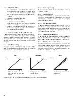
In the service mode, print color patterns on single
sides of 4 to 5 cards. And then remove the film cas-
sette.
Adjust so that the distance from the black marker
on the film to the remaining vertical line (P) is about
8.5 mm. (Check the third to fifth cards.)

