40
2.3.2 Printing Side
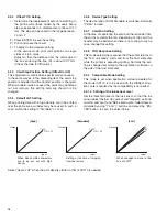
Selection whether test printing is to be done on one side
or both sides.
2.3.3 Times
The number of cards for the test contents selected by "Test
select" of the following item is selected.
2.3.4 Test Select
The test to be executed is selected.
1) Print
Select this for printing and press "ENTER" twice to
start.
2) Feed
Select this to test only the card feed.
3) IC (contact)
The cards are fed and the contact for clip card is
lowered. There is no data communication.
4) IC (Antenna)
The card is fed and stops under the antenna for con-
tact-free clip card.
5) MG (JIS), MG (ISO)
Data actually are written to and read from magnetic
stripe cards. An error is displayed on the LCD panel
in case of abnormalities.
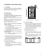
2.4 Diag. Test
2.4.1 Sensor
Correct operation of the sensor is checked.
Confirm the valve is changed, when the sensor is inter-
rupted or reflected.
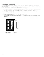
D0: NOCD (no card) ................................................. Reflection: 0
D1: CDIN (card supply) ............................................ Interruption: 0
D2: MGCDPOS (MG card position) ......................... Reflection: 0
D3: TURNCD (turnover card) ................................... Interruption: 0
D4: TURNPOS (turnove initial position) ................... Interruption: 0
D5: EDGE (card edge) ............................................. Interruption: 0
D6: CDOUT (card outlet) .......................................... Interruption: 0
D7: CDNE (card near empty) ................................... Reflection: 0
D8: INK (ink start position)
.................... Transmission (yellow,magenta):0,Interruption: 1
D9: MEDIA (retransfer film mark) ............................. Interruption: 0
D10: CAM (cam position) ......................................... Interruption: 0
D11: HR0POS (retransfer heat roller position) ......... Interruption: 0
D12: HR1POS (bend remedial heat roller position) . Interruption: 0
D13: Not used
D14: Not used
D15: Not used
2.4.2 Actuator
It is possible to operate each motor individually and to check for mo-
tor defects and to check the operation of the mechanisms.
When two cassettes or a door are open, the power supply to the
motor is cut, it will not operate, and inspection should be performed.
1) Ink TUP Mo. (ink take-up motor)
** Remove the inkribbon cassette.
When “OK?” is displayed, press the “ENTER” but-
ton to perform take-up operation.
2) Ink SPY Mo. (ink supply motor)
** Remove the inkribbon cassette .
When “OK?” is displayed, press the “ENTER” but-
ton to perform supply operation.
3) Media TUP Mo. (retransfer film take-up motor)
** Remove the retransfer film cassette.
When “OK?” is displayed, press the “ENTER” but-
ton to perform film take-up operation.
4) Media SPY Mo. (retransfer film supply motor)
** Remove the retransfer film cassette.
When “OK?” is displayed, press the “ENTER” but-
ton to perform film supply operation.
5) Card Feed Mo. (card feed motor)
The card feed motor operates and the roller rotates.
6) Turn Over Mo. (turnover motor)
The turnover motor operates and the turn unit moves
through one cycle.
7) Turn Feed Mo. (turnover card feed motor)
The turnover card feed motor operates and the roller
in the turnover unit rotates.
8) Heat Cam Mo. (cam motor)
The cam motor operates and the retransfer roller and
the bend remedial roller move through one cycle.
9) Pick Up Mo. (card pickup motor)
** The card pickup motor does not rotate when there
is no cleaning roller unit.
The card pickup motor operates and the card
supply roller rotates.
10) Platen solenoid
The solenoid becomes ON (plunger pulled) once and
pushes the platen against the thermal head.
11) Ink TUP Enc. (ink take-up encoder)
** Remove the ink ribbon cassette .
The ink FG sensor is checked. The buzzer sounds
in case of an abnormality.
12) Ink SPY Enc. (ink supply encoder)
** Remove the ink ribbon cassette.
The ink supply encoder (inside the motor) is
checked. The buzzer sounds in case of an ab-
normality.
13) Media TUP Enc. (retransfer film take-up encoder)
** Remove the retransfer film cassette.
The film take-up (inside the motor) is checked.
The buzzer sounds in case of an abnormality.
>>
Sensor
D15
D0
1 0 0 0 0 1 0 1 0 1 0 1 0 1 1 0

