41
2.4.3 Memory
The picture memory SDRAM on the Main PWB is tested.
The buzzer sounds in case of an error. The error LED also
will light.
2.4.4 SIO
A special jig is connected and the terminals OPTION 1
and 2 are tested. Normally this is used for inspection at
the time of shipping from the factory.
2.4.5 Display
All the dots of LCD are displayed black.
Conferm that there is no missing dot.
2.4.6 Back Color
The back colors red, green, and blue are displayed for 3
seconds and correct display of the back colors is tested.
2.4.7 Buzzer
Correct sounding of the electronic buzzer is tested.
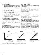
2.4.8 Registers
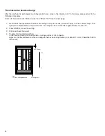
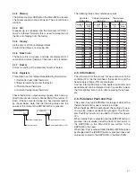
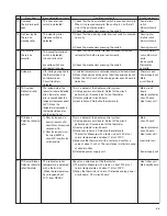
This printer has four temperature-detecting thermistors:
1) Retransfer heat roller thermistor
2) Bend remedial heat roller thermistor
3) Thermal head thermistor
4) Ambient temperature thermistor
These thermistors output analog signals, which are ap-
plied to the circuits for four channel 8bit A/D converter IC.
Each of these converted value in a hex decimal number
as shown below. Note that the following values are the
values at the moment the ENTER button is pressed.
The following table shows reference values.
2.5 Information
The information for the various firmware versions can be
confirmed. For the thermal head, the serial No. and the
head supply voltage (Vth) are displayed.
And the total lighting time of the heaters (retransfer and
bend remedy) can be displayed. And it is possible to clear
the total lighting time to zero after replacing those heat-
ers.
2.6 Parameter Push and Pop
This printer has two EEPROMs for storage of data for the
thermal head and for user and service mode.
When the Main PWB is exchanged, the settings for user
and service mode must be done over again. The Param-
eter Push/Pop function is provided to shorten this opera-
tion.
When initially Push is selected and the [ENTER] button is
pressed, the set values (including head, total countor) in
the EEPROM on the Main PWB are written to the
EEPROM in the head.
When then “Pop” is selected after the Main PWB has been
exchanged and the [ENTER] button is pressed, these set
values are copied to the EEPROM on the Main PWB.
Ambient temperature
Thermal head
Retransfer heat roller
Bend remedial heat roller
>>ADPORT0
C277
>>ADPORT1
FCFC
Heat roller
thermistors
0
20
50
80
100
130
140
150
160
170
180
190
200
210
220
FE
FC
F6
E4
CF
A3
93
82
72
64
56
4A
3F
36
2E
Ambient temperature
thermistor
Thermal head
thermistor
-5
0
10
15
20
25
30
35
40
45
50
55
60
65
75
F2
D9
AC
98
86
76
68
5B
50
46
3D
36
2F
2A
25
0
5
10
15
20
25
30
35
40
45
50
55
60
65
70
E8
E2
DB
D3
C9
BF
B4
A8
9C
90
83
77
6C
61
57
Indicated
Value
Temperature
(
°
C)
Indicated
Value
Temperature
(
°
C)
Indicated
Value
Temperature
(
°
C)

