69
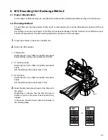
1.
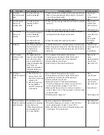
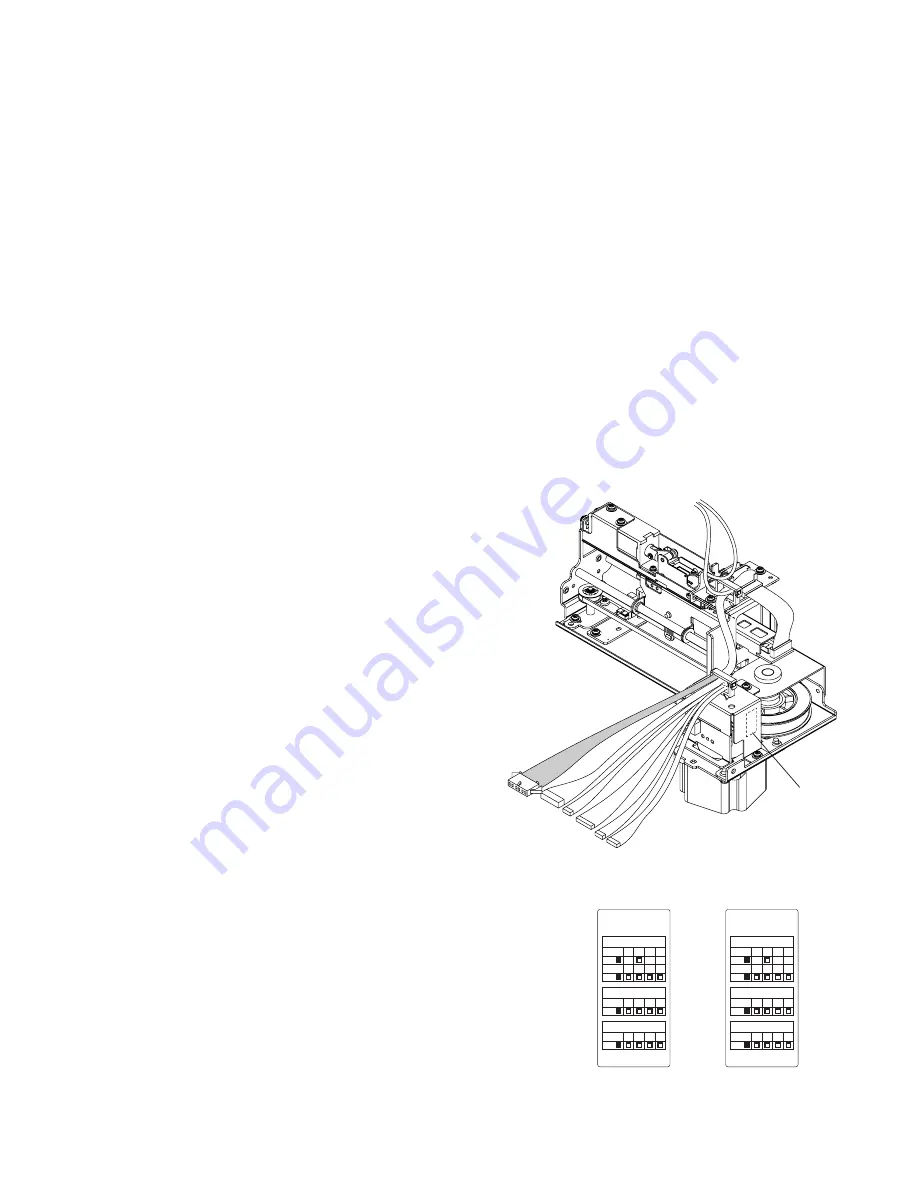
Check the contents of the seal on the MG unit.
2.
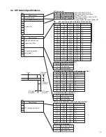
Switch the DIP switches.
1) TRK position
Switch the bits 1 to 4 of SW2 on the MG main circuit
board. Set the switches with a black mark to ON.
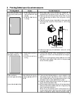
2) IC contact position
Switch the bits 5 to 8 of SW2 on the MG main circuit
board.
Set the switches with a black mark to ON.
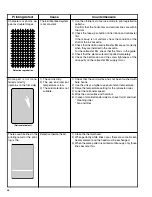
3) STX position
Switch the bits 1 to 4 of SW3 on the MG main circuit
board.
Set the switches with a black mark to ON.
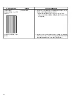
3.
Install the MG main circuit board or the MG unit in
the printer.
Depending, on the way how the MG unit was in-
stalled, an error in the value of track position may
happen.
In that case, confirm of each value and re-adjust in
the following steps.
3. MG Encoding Unit Exchange Method
3.1 Repair Classification
For the repair of MG encoding unit, send-back the whole printeri ncludeing the MG encoding unit to the factory .
3.2 Exchange Method
For each MG unit, the track position (TRK), the IC contact position (IC), and the MG write start position (STX) are
different.
Accordingly, when the circuit board or the MG unit has been exchanged, the DIP switches on the MG main circuit
board must be switched. The DIP switch specifications are shown on the next page.
Seal
I S O
TRK
SW1
ON
- 2 - -
-
- -
SW2
ON
1 2 3 4
IC
SW2
ON
5 6 7 8
STX
SW3
ON
1 2 3 4
KXL46276-004
J I S
TRK
SW1
ON
- 2 - -
-
- -
SW2
ON
1 2 3 4
IC
SW2
ON
5 6 7 8
STX
SW3
ON
1 2 3 4
KXL46276-005
or

