71
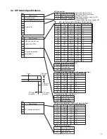
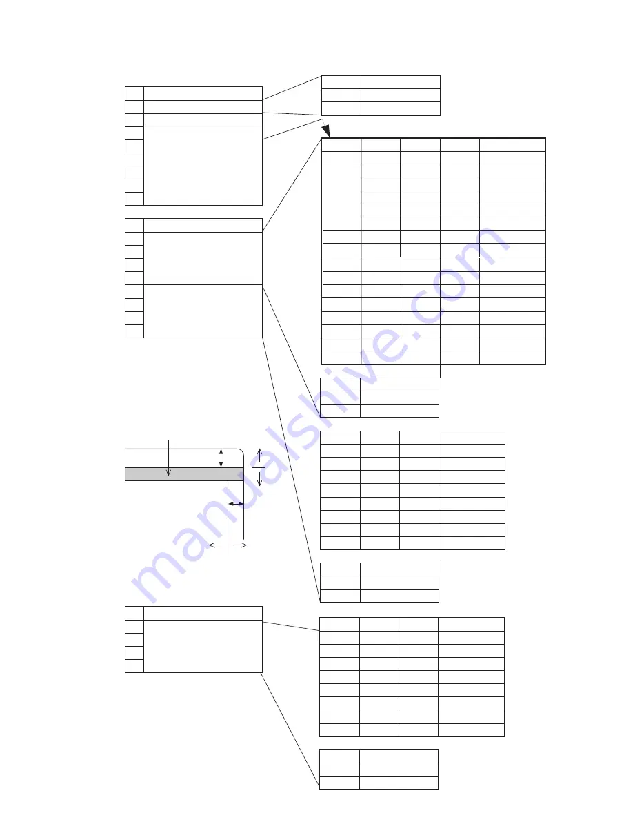
3.3 DIP Switch Specifications
No
1
2
3
4
5
6
7
8
Specifications
MG head select
SW1
No.1
ON
OFF
ON
OFF
ON
OFF
ON
OFF
No.2
ON
ON
OFF
OFF
ON
ON
OFF
OFF
No.3
ON
ON
ON
ON
OFF
OFF
OFF
OFF
Adjustment value (mm)
0
0.1
0.2
0.3
0.4
0.5
0.6
0.7
MG card stop position adjustment (track position)
No.1
ON
OFF
Head specifications
ISO head installed
JIS head installed
MG head select
No
1
2
3
4
Specifications
STX position adjustment
Fixed to ON
No
1
2
3
4
5
6
7
8
Specifications
MG card stop position adjustment (TRK)
SW2
IC card stop position
adjustment
SW3
No.4
ON
OFF
Adjustment direction
Plus direction
Minus direction
MG card stop position adjustment
No.5
ON
OFF
ON
OFF
ON
OFF
ON
OFF
No.7
ON
ON
ON
ON
OFF
OFF
OFF
OFF
No.8
ON
OFF
Adjustment direction
Plus direction
Minus direction
IC card stop position adjustment
No.6
ON
ON
OFF
OFF
ON
ON
OFF
OFF
Adjustment value (mm)
0
0.2
0.4
0.6
0.8
1
1.2
1.4
IC card stop position adjustment (IC contact position)
No.1
ON
OFF
ON
OFF
ON
OFF
ON
OFF
No.3
ON
ON
ON
ON
OFF
OFF
OFF
OFF
No.4
ON
OFF
Adjustment direction
Plus direction
Minus direction
STX position adjustment
No.2
ON
ON
OFF
OFF
ON
ON
OFF
OFF
Adjustment value (mm)
0
0.25
0.5
0.75
1
1.25
1.5
1.75
STX position adjustment (data write start position)
TRK minus
direction
STX minus
direction
STX plus
direction
TRK plus
direction
Never touch the bits 2 to 8.
Always use the unit with these
switches set to ON.
When these switches are set to OFF,
an MG-related error
will be caused at the time of power ON.
Track
MG card stop position
adjustment (TRK)
ON
ON
OFF
OFF
ON
ON
OFF
OFF
ON
ON
ON
ON
OFF
OFF
OFF
OFF
0.8
0.9
1.0
1.1
1.2
1.3
1.4
1.5
SW1No.2
ON
ON
ON
ON
ON
ON
ON
ON
OFF
OFF
OFF
OFF
OFF
OFF
OFF
OFF
ON
OFF
ON
OFF
ON
OFF
ON
OFF

