3
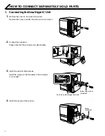
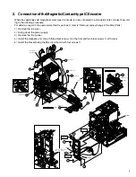
2. Connection of the Magnetic/Contact-type IC Encoder
When the separately sold magnetic/contact-type IC encoder is to be connected to a standard printer, connect it accord-
ing to the following procedure.
For details in regard to the removal method for each part, refer to “Removal and exchange of the Main Parts”.
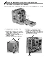
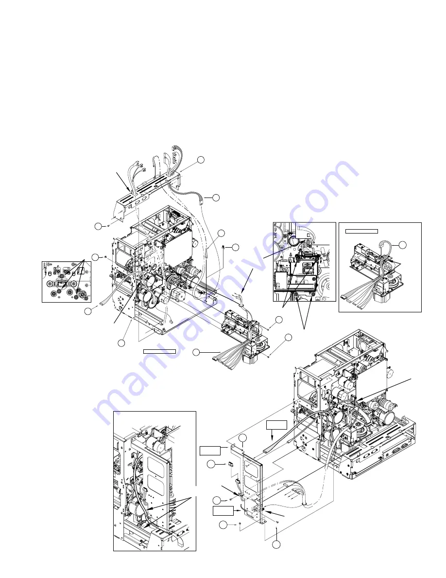
1) Remove the top cover.
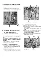
2) Swing down the power supply.
3) Remove the front panel.
4) Install the magnetic unit. Fix with three black screws
8
at the front and four black screws
8
at the rear.
5) Install the bracket fixing the MG circuit board with four screws
6
.
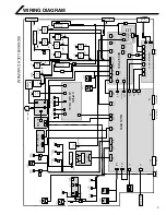
Pass the wires of
power switch.
Explanation drawing 1
CN12
11
KWR17110-001
9
x6
8
8
8
12
KWR18416-001
(TSA0141)
2
1
(TFA0023)
G.NO.004
6
J9
J10
14
KWS0767-002
KWS0768-001
J14
J10
J14
J10
15
13
KWS0744-001
J14
J10
CN3
Clamp
Explanation drawing 1
Clamp
Clamp
Explanation
drawing 1
MG PWB SA
Explanation
drawing 2
6
6
6
J1
CLAMP
6
8
CLAMP
J7
J3
J5
J4
J8
3pin
CLAMP
Explanation
drawing 2
Make the cable routed
away from the rail


