75
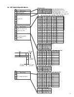
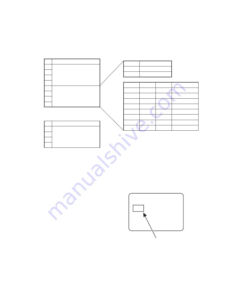
3. DIP Switch Specifications
3.1 Specifications
Do not touch bits 1 to 4 of SW1 and SW2. Always use the unit with these bits set to ON. When these are set to OFF,
an IC-related error will be caused at the time of power ON.
3.2 IC Card Stop Position Adjustment
This adjustment is required when the positioning sensor for contact IC cards or the IC contact has been exchanged.
1.
Contact label is attached on the IC chip.
2.
Use the service mode “Offline Test” to test the external IC unit. Repeat the test 2 or 3 times, so that contact scratches
can be observed easily.
No
1
2
3
4
5
6
7
8
Specifications
Fixed to ON
IC card stop position adjustment
SW1
No.6
ON
OFF
ON
OFF
ON
OFF
ON
OFF
No.7
ON
ON
OFF
OFF
ON
ON
OFF
OFF
No.8
ON
ON
ON
ON
OFF
OFF
OFF
OFF
Adjustment value (mm)
0
0.18
0.36
0.54
0.72
0.90
1.08
1.26
Contact IC card stop position adjustment
No.5
ON
OFF
Adjustment direction
Plus direction
Minus direction
Contact IC card stop position adjustment
No
1
2
3
4
Specifications
Fixed to ON
SW2
CONTACT LABEL:(PART NO.KXL46372-001)

