76
3.
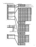
After completion of the test, measure the contact scratches on the CONTACT LABEL with slide calipers and confirm
that the above “a” and “f” are within the standard.
4.
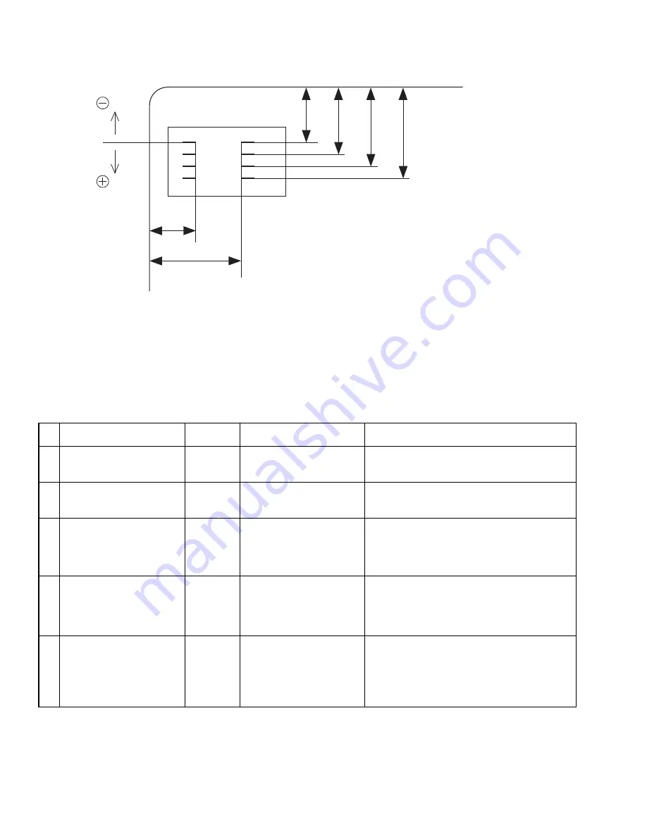
When the values of “c” to “f” are outside the standard, first set the direction with bit 5 of SW1, and then set the
adjustment value with bits 6 to 8. The value of “c” to “f” can be adjusted, and "a" and "b" are only checked because
it cannot adjust.
4. Error Messages
(Standard)
direction
direction
c
a
b
d
e
f
a : 10.25~12.25 mm
b : 17.87~19.87 mm
c : 19.23~20.93 mm
d : 21.77~23.47 mm
e : 24.31~26.01 mm
f : 26.85~28.55 mm
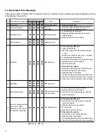
No
Printer LCD indication
Cause
IC unit
LED (D1)
EXT.Unconnected
EXT.SW Setting
EXT.jam
EXT.Communicate
No error message (when an
error has been detected on
the side of the personal
Lit
Blinking
Blinking
Blinking
Not lit
Disconnection 24V line
Switch setting error
Jam error
Communication error with
the printer
IC encoding error
Treatment
1) Is the printer I/F cable connected correctly?
2) Defective IC main circuit board
3) Is 24V output by the printer?
1) Are the DIP switch settings on the IC main
circuit board correct?
2) Defective IC main circuit board
1) Is card feed performed correctly?
¥ Card feed motor
¥ Defective IC main circuit board
¥ Defective card position sensor
¥ Dirty feed roller
1) Is the printer I/F cable connected correctly?
2) The IC main circuit board or the analog
circuit board of the printer unit is defective.
(Caused by connecting/disconnecting the printer
I/F cable while the power is on,)
1) Are the DIP switch settings on the IC main
circuit board correct?
2) Confirm the IC card setting direction.
3) Defective IC main circuit board
4) Check the card feed roller for dirt and clean
1
2
3
4
5


