83
<
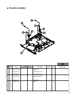
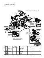
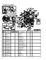
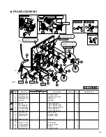
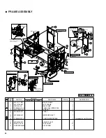
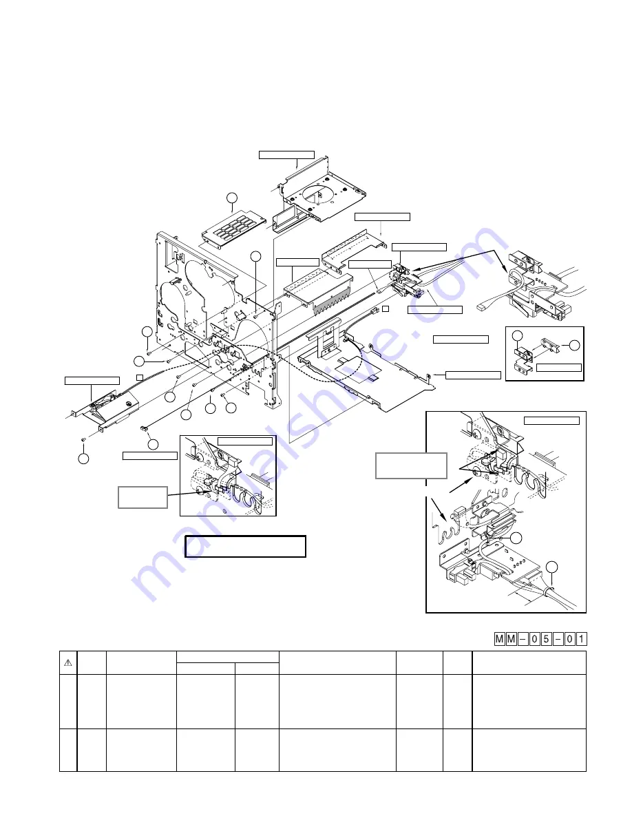
FRAME ASSEMBLY
1
KJP33144-C01
MEDIA FRAME
1
2
KJP45549-B01
GUIDE BKT
1
3
KJM33160-001
SIDE GUIDE
1
4
5
YMC-05-H-0
MINI CLAMP
1
6
KJJ46271-003
TAP SCREW
12
7
8
AN-1
BINDER
2
9
SYMBOL
NO.
PART NO.
REVISED
PART NO.
Rev.
PRICE
PART NAME
QTY
DESCRIPTION
8
About 10mm
8
1.Bind the sensor cable
with a binder using
the hole in the blacket.
Wire clamping
Front side
2.Clamp the sensor
cable so that the
edges of the
connector and the
adjacent bracket
are on the same
level.
Explanation drawing 9
FRONT SENSOR SA
6
6
6
6
DUCT FRAME SA
Explanation drawing 1
2
MEDIA FRAME
6
HEAD RAIL SA
INK FRAME SA
1
6
F1
6
6
Take out the cable
from a front side
and clamp it.
5
Note that the half punch does not get on BKT
when you fix the BKT by screw.
Refer to front page for Explanation drawing 1 to 7.
CENTER FRAME SA
F1
Pass the wire through the
notch in the bracket.
1
3
GUIDE SA
GUIDE SA
Explanation drawing 3
Explanation drawing 6
Explanation drawing 8
Explanation drawing 8
Explanation drawing 7
Explanation drawing 2
Explanation drawing 8
Explanation drawing 4
Explanation drawing 9
Explanation drawing 9
Explanation drawing 9

