(No.HD001<Rev.001>)1-11
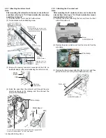
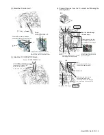
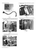
(3) Close back the MAIN Board to its original position, and fix
the MAIN Board with the four screws.
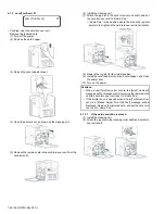
(4) Connect the wires from the MG unit and the turn unit follow-
ing the drawing below.
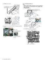
2.5.5 Attaching the IC R/W unit
Note:
After mounting the IC R/W unit, be sure to check the rele-
vant item referring to "2.6 Check details after mounting
separately sold parts".
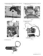
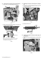
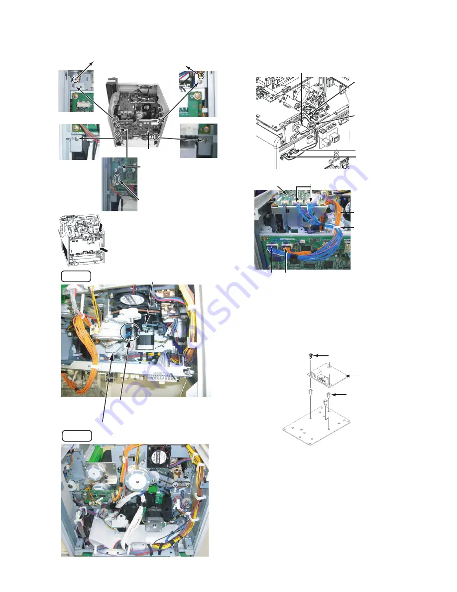
(1) Attach the IC R/W unit to the plate.
A
B
View B
View A
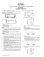
Make sure that the wires do not touch the encoder.
Opened MAIN Board
Organize the head wire so that it does not
touch the rotating parts such as belts/gears,
and then fix the head wire with the wire clamp.
The cam gear and the wire should be parted.
MAIN Board
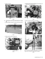
Securely hook the two brackets, fixing the
MAIN Board, to the frame of the main unit.
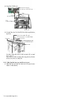
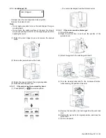
Coaxial connector
Make sure that the coaxial
connector is not loose.
Allow about 5 mm slack to
enable the cable to move.
Wire from the turn unit CN1
Connect the MG unit and the board bracket, and fix them with screws.
Wire : QUB030-05HMHM-E
Screw : QYSDST3006NA x 2
Run the wires from the turn
unit and the MG unit together
through this wire clamp, and
fix them.
MAIN Board
CN19
CN15
MG UNIT
Wire from the
turn unit CN1
Wire clamp
MAIN Board
MAIN Board
MAIN Board
CN19
CN15
MG Unit
MG unit accessories
IC R/W Unit
QYSPSPH3006NA x 3
QZW0326-002 x 3
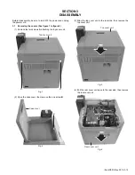
Summary of Contents for XID 8300
Page 1: ...No HD001 Rev 001 2010 10 SERVICE MANUAL CARD PRINTER XID8300 XID8300 DS XID8300C XID8300C DS ...
Page 46: ......
Page 56: ......


