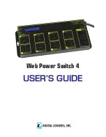
Web Power Switch 4
Ethernet Power Controller III
www.digital-loggers.com
7
6
Setup
The setup page lets you select outlet names, program web link s,
startup delays, and the power loss recovery mode. You can also
change login credentials on this page.
Scripting
A scripting language using BASIC commands lets you
customize the power controller. Scripts may be started manually,
automatically on power-up, by external http commands, or by
Auto-Ping events. Find a full list of commands and example
scripts at:
www.digital-loggers.com/scripting.html
AutoPing
The AutoPing link lets you set parameters for automatically reboot
attached equipment. First specify an IP address to ping. Next
adjust the timing settings and use the checkboxes to link the IP to
specifi c circuits. For example, if a router is unreachable, you may
choose to automatically reboot both a router and a switch attached
to two different circuits. Learn more:
www.digital-loggers.com/
autoping.html
System Log
The power controller keeps a log of system events including logins
(successful and attempted), outlet switching, power interruptions,
and Auto-Ping events. Recent events are stored in the log and
accessible from the System Log page. Multiple controllers can
export logs to a single external SYSLOG server. Find information
on setting up a SYSLOG server here:
www.digital-loggers.com/
syslog.html
Logout
The controller will automatically log-out when your browser
session is closed. Click this link to log-out in advance.
Help
The Help link displays the latest online manual. Since features are
subject to change without notice, this manual may not be an exact
match for earlier controllers and earlier fi rmware versions. Find the
fi rmware revision history at
www.digital-loggers.com/revhistory.html
Windows 7, Vista
Click
Start
->
Control Panel
. In the search box, type
adapter
.
Under “Network and Sharing Center”, click
View Network
Connections
. Right click on the adapter you’re using and click
Properties
. Click the
Networking
tab. Select
Internet Protocol
Version 4 (TCP/IPv4).
Click
Properties
,
Advanced
, then under
IP addresses click
Add
.
Enter a new compatible IP, such as
192.168.0.1, and a subnet mask of 255.255.255.0. Press
Add
.
Close all windows for the confi guration to take effect. Start your
Browser and type 192.168.0.100 in the URL fi eld. Log in.
Basic Operation
After power-up, the controller performs a sequence of self-tests to
ensure reliability. The static IP on the
Settings
page is used.
The controller may then be operated via a web browser. To access
the controller, simply enter the IP address in the URL fi eld of your
web browser. The default is
http://192.168.0.100
Home (Outlet Control) Page
To access the home page, fi rst enter the IP address in web
browser URL fi eld, then log in. User
admin
has access to all
features. Other users have limited access to outlets as assigned
by the administrator. When confi guring the power controller for the
fi rst time, use the default admin username and
1234
password.
The home page contains 11 links to other pages. The fi rst nine are
fi xed internal links:
Outlet Control
Clicking “Outlet Control” links to the home page used for manually
switching outlets on and off. Access to specifi c outlets is
determined by your login.


