background image

24


INSTALLATION


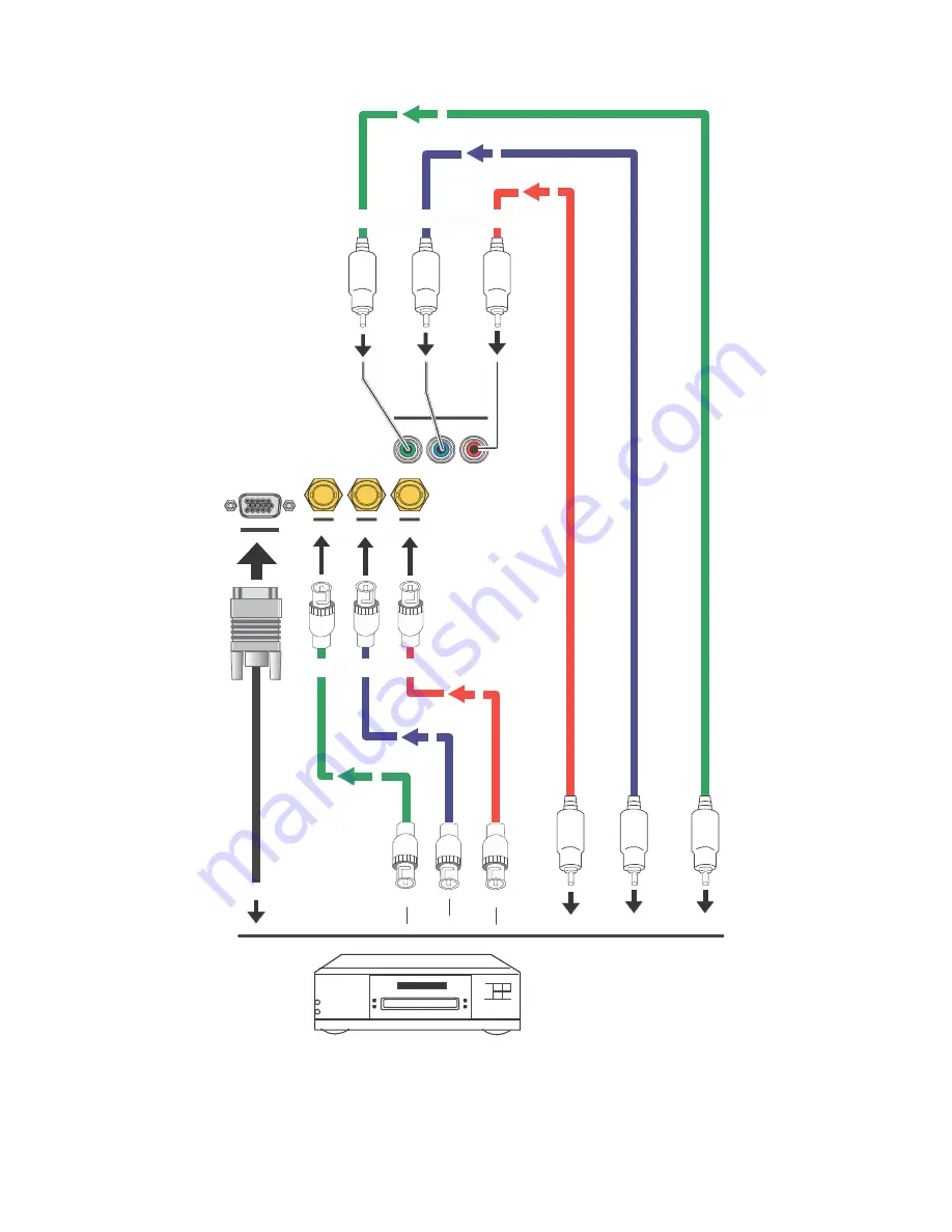
Component Video Connections: Connect your component video sources to the COMPONENT 1/SCART,


COMPONENT 2 or RGB inputs as shown in Figure 3-9.


Pb  

Pr


COMPONENT 

SCART


RGB


Pb  

Pr


COMPONENT 

2


Pb  

Pr


DTV Set-Top  Box or 
Other Component 
(YPbPr) Source


Figure 3-9: Component Video Connections


Summary of Contents for M-Vision

Page 1: ...M Vision Operation Manual Digital Projection Incorporated 55 Chastain Road Suite 115 Kennesaw GA 30144 770 420 1350 www digitalprojection com Publish Date 11 14 2009 PRELIMINARY ...

Page 2: ...ol 14 Notes on Batteries 14 Notes on Remote Control Operation 14 3 2 Quick Setup 15 3 3 Installation Considerations 16 Installation Type 16 Ambient Light 16 Throw Distance 17 Vertical and Horizontal Position 18 Folded Optics 20 Other Considerations 20 3 4 Mounting the Projector 21 Floor Mounting Upright 21 Adjusting the Projection Angle 21 3 5 Connections to the projector 22 Connecting Source Comp...

Page 3: ...atio 31 4 2 Selecting An Input Source 31 Operation 31 4 3 Using the On Screen Menus 32 Main 34 Advanced 42 System 47 Control 49 Language 50 Service 51 5 1 Lamp Replacement 53 Maintenance and Troubleshooting 53 5 2 Cleaning the filters 54 Cleaning the fans 54 Replacing the optional filter 54 5 3 Troubleshooting Tips 55 Serial Interface Specifications 56 6 1 Transfer Specifications 56 7 1 Projector ...

Page 4: ...g is provided for your safety When the provided plug does not fit into your outlet consult an electrician for the replacement of the obsolete outlet 9 Protect the power cord from being walked on or pinched particularly at plugs convenience receptacles and the point where they exit from the apparatus 10 Only use the attachments accessories specified by The company 11 Use only with a cart stand trip...

Page 5: ...tion 5 Surge immunity test EN 61000 4 6 Electromagnetic compatibility EMC Part 4 Testing and measurement techniques Section 6 Conducted disturbances induced by radio frequency fields immunity test EN 61000 4 8 Electromagnetic compatibility EMC Part 4 Testing and measurement techniques Section 8 Conducted disturbances induced by power frequency magnetic fields immunity test EN 61000 4 11 Electromag...

Page 6: ...anadian ICES 003 Cet appareil numérique de la classe B est conforme à la norme NMB 003 du Canada IMPORTANT RECYCLE INSTRUCTIONS Lamp s inside this product contain mercury This product may contain other electronic waste that can be hazardous if not disposed of properly Recycle or dispose in accordance with local state or federal Laws For more information contact the Electronic Industries Alliance a...

Page 7: ...vided Remote button identifiers are set in upper case bold type for example Press EXIT to return to the previous menu Computer input commands you type and output responses that appear on screen is shown in monospace fixed width type for example To change the aspect ratio to Letterbox type op aspect 1 Enter All keys with functional names are initial capped set in bold type and enclosed in angle bra...

Page 8: ...engineered for the top quality 1080p picture performance and installation flexibility heretofore associated with projectors costing far more This Full HD 1920 x 1080 native resolution DLPTM light engine projector features state of the art technology for bright pristine high definition images at today s highest available resolution This projector is equipped with a precision optics package offering...

Page 9: ...e Two 2 HDMI 1 3 Inputs with High bandwidth Digital Content Protection HDCP HDTV Compatible Parts List Your projector is shipped with the following items If any items are missing or damaged please contact your dealer This 1080p DLP Projector Remote Control Unit and two 2 AA size batteries One AC Power Cord North America Allen wrench for image shift adjustment Optional Accessories Replacement lamp ...

Page 10: ...T Figure 2 1 Projector Front Side View Warm air exits the projector through this vent Ensure that it is not blocked INTAKE VENT Internal fans draw cool air into the projector through this vent ZOOM RING Rotate this to change the projected image size FOCUS RING Rotate this to focus the projected image PROJECTION LENS Available in two versions standard throw range 1 85 1 to 2 40 1 short throw range ...

Page 11: ...he pro jector to a table or mounting plate to prevent accidental movement Below drawing is the mechanical dimension for you to design a mounting plate RS 232 1 H DMI 1 H DMI 2 12V TRIGGER 1 2 IR INPUT S VIDEO VIDEO COMPONENT 1 SCART RGB Y Pb Pr COMPONENT 2 AC POWER IN 2 3 4 PROJECTION LENS The inside of the lens barrel is threaded to ac commodate a standard 72 mm lens filter For example with a sma...

Page 12: ... or high definition 480i 480p 576i 576p 720p 1080i 1080p Component YPrPb input for connecting a DVD HD DVD BD player HD set top box or other SD HD source Also provides RGB input for RGBS sources 6 VIDEO Standard composite video input for connecting a VCR laser disc player or other composite video source Also provides composite sync input for RGBS sources 7 S VIDEO A standard S Video input for conn...

Page 13: ...tterns ENTER Press to select a highlighted menu item or confirm a changed setting 5 Aspect Ratio Selection Button Press this button repeatedly to select one of the fol lowing aspect ratios 16 9 Default setting For viewing 16 9 DVDs or HDTV programs in their native aspect ratio Letterbox For viewing LaserDisc movies or non anamorphic DVDs on a 16 9 screen 4 3 Scales the input signal to fit 4 3 sour...

Page 14: ...e correct polarity 3 Replace the cover 1 2 3 Notes on Batteries Make sure that the battery polarities are correct when installing the batteries Do not mix an old battery with a new one or different types of batteries If you will not use the remote control for a long time remove the batteries to avoid damage from battery leakage Notes on Remote Control Operation In most situations you can simply po...

Page 15: ...e projector Connect signal sources to the Projector Connect external controller to RS 232 port and or IR repeater system optional Apply power to the projector Change the OSD Language optional For rear screen and or ceiling mount installations select the proper picture orientation Primary lens adjustments projected image size zoom position shift and focus Projector calibration adjust the following ...

Page 16: ...ce with audience Rear Screen Floor Mount Installation Projector is completely hidden Projector is easily accessed Usually good ambient light rejection Requires separate room Installation cost is usually higher Rear Screen Floor Mount with Mirror Projector is completely hidden Usually good ambient light rejection Requires less space behind screen than other rear screen installations Requires separa...

Page 17: ... 2 The result of this calculation tells you roughly how far back the projector should be positioned from the screen in order to project a focused image large enough to fill the screen Estimating Throw Distance Throw Distance TD Screen Width w x Lens Throw Ratio Figure 3 2 Estimating Throw Distance Two models of the projector are available one with 1 56 1 86 1 lens and the other with 1 85 2 40 lens...

Page 18: ...use the lens shift controls on the projector to center the image on the screen Lens shift is generally expressed as a percentage of the screen height or width as shown in Figure 3 4 and Figure 3 5 Screen Center 0 50 Height Lens Shift 0 5 x H 100 Height Lens Shift 1 0 x H Note This is a general example of lens shift Lenses vary in their shift capabilities No particular lens or projector is used in ...

Page 19: ...shift Lenses vary in their shift capabilities No particular lens or projector is used in this example Figure 3 5 Horizontal Lens Shift Example Only Note 1 With no vertical or horizontal lens shift the lens center and screen center are aligned with each other 2 Vertical shift limits are percentages of the screen height Horizontal shift limits are percent ages of the screen width 3 Vertical lens shi...

Page 20: ...ips that can help improve your installation Keep the ambient temperature constant and below 35 C 95 F Keep the projector away from heating and or air conditioning vents Changes in temperature may cause drifts in the projector circuitry which may affect perform ance Keep the projector away from devices that radiate electromagnetic energy such as motors and transformers Common sources of these inclu...

Page 21: ...tion or from site to site If possible lock the wheels when it s in position to prevent it from being moved during a presentation Adjusting the Projection Angle If the screen is significantly higher or lower than the projector you can also tilt the projector at a slight angle In a ceil ing installation you do this by adjusting the ceiling mount For a floor installation turn the adjustable feet at t...

Page 22: ...es for each source Ensure that the cables are securely connected Tighten the thumbscrews on connectors that have them Connecting Source Components to the projector Connect your video sources to the projector as shown and described in the sections that follow HDMI DVI Connections See Figure 3 7 HDMI 1 HDMI 2 HDMI or DVI Source s BD HD DVD DVD Player HD Set Top Box Game Console etc Figure 3 7 HDMI D...

Page 23: ...GB with composite sync connect the green blue and red outputs to the Y Pb and Pr terminals on the COMPONENT 1 SCART input and the sync output to the VIDEO input See Figure 3 8 Sync Green Blue Red DVD Player or Other SCART RGBS Source 12V TRIGGER 1 2 IR INPUT S VIDEO VIDEO COMPONENT 1 SCART Personal Computer Figure 3 8 RGB Connections ...

Page 24: ...ct your component video sources to the COMPONENT 1 SCART COMPONENT 2 or RGB inputs as shown in Figure 3 9 Y Pb Pr COMPONENT 1 SCART RGB Y Pb Pr COMPONENT 2 Y Pb Pr DTV Set Top Box or Other Component YPbPr Source Figure 3 9 Component Video Connections ...

Page 25: ...mposite S Video Connections Connect your Composite and S Video sources to the projector as shown in Figure 3 10 S VIDEO VIDEO DVD Player VCR Satellite Receiver Laser Disc etc Figure 3 10 Composite and S Video Connections ...

Page 26: ...tor see Figure 3 11 Use a standard 9 pin serial cable wired straight through For more information about using this connection refer to Serial Communications on page 67 5 4 3 2 1 9 8 7 6 RS 232 2 Transmit Data 3 Receive Data 5 Ground none of the other pins are used to Automation Control System or PC Figure 3 11 RS 232 Control System Connection ...

Page 27: ...gure 3 13 IR Sensor IR Repeater Remote Control 3 5 mm mini phono plug IR INPUT S VIDEO VIDEO COMPONENT 1 SCART Figure 3 12 External IR Receiver Connection Connecting to AC Power The projector ships with one AC power cord If you need a different cord find one that is appropriate to your locate that has a IEC Female plug to interface to the projector side Plug the female end of the power cord into t...

Page 28: ...3 When the projector is ready for use the LED turns off 3 7 Changing the OSD Language When you turn on the projector for the first time the OSD Language Menu appears The projector can display the menus in English French German Italian Spanish Swedish Traditional Chinese Simplified Chinese Japanese Korean Portuguese or Russian Press or to select a language Then press ENTER to confirm your selection...

Page 29: ... Then select System from the Main Menu Rear Projection If the projector is used in a rear projection application see Figure 3 6 press repeatedly to select Rear Projection from the System Menu Press or to set it to On 3 9 Lens Adjustments The projector gives you a great deal of control over the picture size position and focus Focus To focus the projected image grasp the lens by the front ring and r...

Page 30: ... the projected image vertically insert the provided Allen wrench into the hole at the top of the projector directly above the lens Then turn the wrench to shift the lens in the desired direc tion Horizontal Image shift To shift the pro jected image horizontally insert the provided Allen wrench into the hole at the top of the projector Then turn the wrench to shift the lens in the desired direction...

Page 31: ...ut Source When you turn on the projector it switches to the last selected in put and looks for a valid signal Use these buttons on the remote control to select an input source directly You can assign each of these five buttons to any input The default assignments are 1 RGB VGA HD15 2 HDMI 1 3 HDMI 2 4 Component 1 5 S Video For more information refer to 1 Key 2 Key 3 Key 4 Key 5 Key on page 56 ...

Page 32: ... For each sub menu item the currently selected value appears in white text or is otherwise highlighted Press or to choose a setting for that item or press ENTER to go to another sub menu 5 Press MENU to return to the previous menu 6 From the Main Menu press MENU to turn off the OSD menu The projector OSD menus are arranged hierarchically as shown in Figure 4 1 Depending on the selected input sourc...

Page 33: ...rature This item has no function DLP Frame Rate Auto 48 Hz 50 Hz or 60 Hz Color Gamut Auto REC709 SMPTE C EBU or Native Adaptive Contrast On or Off Red Green Blue Offset RGB Adjust Red Green Blue Gain V Position H Position Phase Tracking Advanced Fine Sync Sync Level Source Enable On or Off for each source PIP Position NA Menu Position Top Left Top Right Bottom Left Bottom Right or Center Auto Pow...

Page 34: ...e on the active source Figure 4 2 Projector Main Menu Aspect Ratio To change the aspect ratio size and shape of the projected image press or to highlight Aspect Ratio Use the or buttons to select the appropriate aspect ratio for your screen size installed lens configuration and the type of program material being viewed then press ENTER refer to Table 4 2 ...

Page 35: ...ttings Unless you select Default see below this control affects all sources not just the active source User Memory 1 and User Memory 2 contain the factory default settings when the projector is initially turned on Choose Default to restore the factory default settings for the active source only The other sources are unaffected Save Settings Select Save Settings from the Memory menu to save any ima...

Page 36: ...Gamma DLP Frame Rate Color Gamut Adaptive Contrast RGB Adjust all settings in sub menu The settings that are saved are the same as those saved with the Save Settings command see above Brightness On your external test pattern source select a PLUGE pattern PLUGE is an acronym for Picture Line Up Generation Equipment Figure 4 3 shows a typical PLUGE pattern Below Black Above Black Figure 4 3 Typical ...

Page 37: ...bars is consistent with the other bars Note Brightness and Contrast controls are interactive A change to one may require a subtle change to the other in order to achieve the optimum setting Color Saturation To adjust the overall color intensity select Color Saturation from the Main menu Decrease this setting if colors are overly saturated increase it if colors appear muted or washed out Color Tint...

Page 38: ...Mode Noise Reduction Mode allows or prevents access to the detailed noise reduction controls in this menu In most cases Simple mode provides a sufficient level of control to produce the best picture from the most popular sources In Simple mode only the Noise Reduction top most slider is adjustable the others are grayed out Choose Advanced mode if you need more precise control over noise reduction ...

Page 39: ...ction is RGB VGA HD15 All sources that are not available per the source enable function refer to Source Enable on page 54 are grayed out Figure 4 7 Source Select Sub Menu All sources that are not available per the source enable function refer to Source Enable on page 54 are grayed out Resync If the projected image becomes unstable or degraded press or to highlight Resync then press ENTER ...

Page 40: ...gnals are present the projector uses the RGB PC color space Otherwise REC601 is used for SDTV and EDTV sources and REC709 for all other sources Component For SDTV and EDTV resolutions the projector uses the REC601 color space For all other resolu tions REC709 is used In most cases the Auto setting determines the correct color space to use If it does not you can force the projector to use a specifi...

Page 41: ...on that video cam eras use to create images Bright sets the gamma to 2 0 Graphics should only be used for computer presentations that require increased brightness at the cost of grayscale accuracy DLP Frame Rate Select DLP Frame Rate from the Advanced menu to choose the output frame rate You can have the projector automatically determine the optimum frame rate or you can force it to use a specific...

Page 42: ...gs and Associated x y Values REC70 9 SMPTE C EBU Primar y Colo r x y x y x y Red 0 640 0 330 0 635 0 340 0 640 0 330 Yellow 0 419 0 505 0 421 0 506 0 418 0 502 Green 0 300 0 600 0 305 0 595 0 290 0 600 Cyan 0 225 0 329 0 228 0 326 0 220 0 329 Blue 0 150 0 060 0 155 0 070 0 150 0 060 Magenta 0 321 0 154 0 318 0 162 0 328 0 158 Table 4 3 x y Color Gamut Values Adaptive Contrast Adaptive Contrast enh...

Page 43: ...et controls in the RGB Adjust sub menu to correct color imbalances in the dark areas of the im age A good way to do this is to use a test pattern consisting mostly of dark gray areas such as a 30 IRE window pattern If the gray areas contain traces of red green or blue decrease the Offset for that color The Gain controls increase or decrease the full scale input range the Offset controls shift the ...

Page 44: ...is control adjusts the phase of the pixel sampling clock relative to the in coming signal Adjust the phase when an RGB or Component image still shows shimmer or noise after Tracking has been optimized Adjust the Phase after adjusting Tracking see below If some shimmer from a video or HDTV Tip source persists use the Noise Reduction controls described on page 44 to remove high frequency noise from ...

Page 45: ...ly Select Sync Level to adjust the voltage level of the Projector Sync signal de tection circuitry Sync Level adjustment is occasionally necessary when a DVD player or HDTV source signal drops below black for example during scenes with explosions or when subtitles are present and causes the projector to temporarily lose sync If the Sync Level from the source is persistently too low the projector w...

Page 46: ...les or disables the HDMI 1 and HDMI 2 sources RGB Enables or disables the RGB source Comp 1 Comp 2 Enables or disables the Component 1 and Component 2 sources Video Enables or disables the Composite video source If either Component 1 or Video is enabled SCART must be disabled Note S Video Enables or disables the S Video source SCART Enables or disables the SCART RGBS source If SCART is enabled bot...

Page 47: ...wer On to Off this is the default setting Rear Projection This control reverses all images and menus and is necessary when the projector is used in rear pro jection applications The default is Off Control Select Control from the Main Menu to set various options related to control of the projector 1 Key 2 Key 3 Key 4 Key 5 Key These menu items assign the function of the keys numbered 1 through 5 on...

Page 48: ...ntrol chooses whether or not to scan for other active sources if the current source is not available The default setting is off Language Select Language from the Main Menu to change the OSD Language The projector can display the menus in English French German Italian Spanish Swedish Traditional Chinese Simplified Chinese Japanese Korean Portuguese or Russian Press or to select a language Then pres...

Page 49: ... Clock Signal Format H V Refresh Rate Lamp Hours number of lamp hours elapsed since the last reset Should you ever need to contact Technical Support this information will help them answer your questions and or re solve product performance issues Figure 4 14 Projector Service Menu There is no user intervention required to reset the lamp counter subsequent to replacing the lamp module The lamp modul...

Page 50: ...ion measurement and fault isolation purposes To access them select Test Patterns from the Service menu and set it to On The available test patterns are White Black Red Green Blue Cyan Magenta Yellow ANSI Checkerboard Horizontal Gray Ramp Focus Grid Press or on the remote control unit to cycle through the test patterns The OSD menus are not available when in test pattern mode Note To turn test patt...

Page 51: ...ector to cool down for approximately 60 minutes prior to re moving the lamp assembly for replacement 2 Using a flat blade screwdriver loosen the two screws holding the rear compartment cover in place 3 Remove the rear compartment cover by tilting it upward 4 Loosen the screw on the lamp cover and pull the lamp cover out 5 Loosen the two screws on the lamp module 6 Pull the lamp module handle firml...

Page 52: ...fans The projector uses the filter to keep the fans free of dust and other particles and should be cleaned every 500 hours of operation In dustier environments it is recommended to clean the filter more frequently If the filter is dirty or clogged your projector may overheat ...

Page 53: ...at all Select the correct source Turn on the source Check cable connection from source component to projector A projected image from a DVD is split or otherwise scrambled DVD player is connected to the Component input and set to pro gressive scan mode Turn off progressive scan on the DVD player Image is blurred The lens is not correctly focused Adjust the focus with the remote control Image is too...

Page 54: ...56 SERIAL INTERFACE SPECIFICATIONS RS 232 Documentation 7 Full documentation can be downloaded as a separate pdf document in the M Vision document library on www digitalprojection com ...

Page 55: ... TI DMD 0 95 X 1 12 degree DC2 Driver Technology Dual 3021 s Color Wheel 5 segment RYGWB 2X Color Temperature 6500K 1500K Lamp 1 x 260W lamp Projection Lens Short throw lens 1 46 to 1 86 1 or Medium throw ratio 1 85 to 2 5 1 Fixed lens 73 1 Note Values for 1080p w 0 95 Projection Lens Image Offsets Vertical 120 V Horizontal 30 H Image width range 8ft to 30 ft see screen size table Prism DMD Optics...

Page 56: ... Power 100V 240V 50 60Hz 350W max 2W Standby Safety UL 60950 1 RoHS compatible EMI FCC Class A Software Basic User Command List See User Manual Fault Tolerant Ballast Control Standard ballast control Mechanical Engine weight 20 lbs Dimensions 351 W x 394 D x 165 H mm 14 2 x 15 5 x 6 5 inches Enclosure Table or rack mounted open rack only Adjustable feet 2 max travel Reliability Operating Temperatu...

Page 57: ......

Page 58: ...00 ü ü 1600x1200 1600x1200 60 00 75 000 162 000 ü ü 1680x1050 1680x1050 59 94 69 830 164 240 ü ü 1920x1080 1920x1080 47 95 56 821 150 007 ü ü 480 60i 720x487 59 94 15 734 13 500 ü ü ü 480 60p 720x483 59 94 31 469 27 000 ü ü ü 576 50i 720x576 50 00 15 625 14 750 ü ü ü 576 50p 720x576 50 00 31 250 29 000 ü ü ü 720 50p 1280x720 50 00 37 500 75 250 ü ü ü 720 60p 1280x720 60 00 45 000 74 250 ü ü ü 1080...

Reviews: