background image

Specifications subject to change without notice 

© Digital View Ltd – Doc Ver 1.00:  10 Sept, 2021  

Page 

16 of 46


GROUP 2 


Pos #1


Pos #2


Pos #3


Pos #4


Pos #5


Pos #6


Pos #7


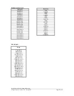
Panel resolution  

OFF 

OFF 

OFF


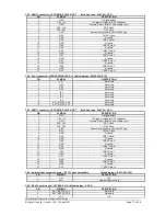
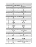
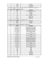
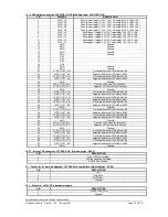
OFF


OFF


OFF


OFF


Sharp LQ235D1LW03 120Hz 


1920x1080 

OFF 

OFF 

OFF 

OFF 

OFF 

OFF 

ON 

LG LM265SQ1-SLA1(Tested)


1920x1920 

OFF 

OFF 

OFF 

OFF 

OFF 

ON 

OFF 

LG LM270WQ1-SDE3 

2560x1440 

ON 

OFF 

OFF 

OFF 

OFF 

ON 

OFF 

LG LM300WQ6-SL01 

2560x1600 


Pos. #8 

Video lock 

ON – Disable : Always fix the output be 60Hz. 
 
OFF – Enable : The output refresh rate locks to the input for 50Hz / 60Hz mode 
(other resolution lock the output be 60Hz. ) 


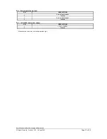
Table 3 : DIP switch selection – SW4 

Pos. # 

Function 

Description 

Panel timing group selection 

OFF : Group 1 for SW3 dip switch setting 
ON : Group 2 for SW3 dip switch setting 

Panel pixel format 

OFF : Double Pixel 
ON   : Single Pixel 

Panel selection 

ON : Single / Double pixel LVDS panel (controlled by SW4 position 2) 
OFF : Four channel LVDS panel


LVDS data mapping select   
(Refer to Table 2) 

If SW4 position 5 = OFF (8 bit) 
OFF : Mapping B  
ON  : Mapping A 
Please adjust to get the correct picture. See as Appendix I for details of 
mapping of A and B.    


If SW4 position 5 = ON (10 bit) 
OFF : JEIDA (LVDS panel)     
ON : VESA (LVDS panel) 
Please adjust to get the correct picture. See as Appendix I for details of 
mapping of VESA and JEIDA.    

Output LVDS display mode selection 

OFF : 8 bit  
ON : 10 bit 

LVDS mapping swap 

OFF : Normal 
ON : Swap 


Support "Resolution default by EDID" for different resolution panel. 
 

The controller will set the preferred timing based off the dip switch setting (SW3 position 1-7) selection, 
but also be able to go higher to 2560x1600. For example, if the panel is a 1024x768 and the dip switch 
setting are set for 1024x768. The preferred EDID resolution should be 1024x768.  It should also have 
the capability to set the max resolution to 2560x1600.   


Summary of Contents for 417800000-3

Page 1: ...controller 10 Connectors pinouts jumpers Essential connection information 22 Controller dimensions 23 Application notes 25 Troubleshooting 26 Specifications 27 Appendix I Supported graphics modes table 30 Appendix II RS 232 control protocols 37 Appendix III Mapping definition 40 Appendix IV Auto Color Gain 41 Appendix V DV remote control unit work for HX 2560 SDI 42 Appendix VI PIP mix table 43 Ap...

Page 2: ...be independently tested and verified by the user Ordering information Controller Part number Ordering part number HX 2560 SDI P N 41780000X 3 P N 4178000XX 3 HOW TO PROCEED Ensure you have all parts that they are correct refer to Connection diagram Connector reference in following section Assembly notes Check controller switch jumper settings errors may damage the panel Prepare the PC Connect the ...

Page 3: ...ications subject to change without notice Digital View Ltd Doc Ver 1 00 10 Sept 2021 Page 3 of 46 SYSTEM DESIGN A typical LCD based display system utilizing this controller is likely to comprise the following ...

Page 4: ...s and different pin assignment Make sure correct cable pin out to match inverter Using wrong cable pin out may damage the inverter 6 Function Controls The following section discusses the controls required and the section on connectors provides the detail The controls are minimal On Off Backlight Brightness depends on inverter OSD 5 momentary buttons or analog VR type or 8 momentary buttons digital...

Page 5: ...e insulation for all circuitry EMI Shielding will be required for passing certain regulatory emissions tests Also the choice of external Controller to PC signal cable can affect the result Ground The various PCB mounting holes are connected to the ground plane Servicing The board is not user serviceable or repairable Warranty does not cover user error in connecting up to the controller and is inva...

Page 6: ...ettings 9 Input signal cable Controller Plug the corresponding signal input to the connector on the controller board 10 SDI input cable Plug the coaxial cable to connector J4 on the controller board for SDI input cable Plug another coaxial cable to J5 for re clock loop out Recommend to connect less than 100 meter in good co axial cable e g Belden 1694A between DV devices 11 Power supply Controller...

Page 7: ...SD menu On or Off it will auto time off Menu button Menu button Select down Moves the selector to the next function down SEL DN SEL DN Select up Moves the selector to the previous function up SEL UP SEL UP Increase the OSD parameter values Moves the selector to next function forward Decrease the OSD parameter value Moves the selector to previous function backward Reset to Factory Defaults Press an...

Page 8: ...ert Off On Invert for the backlight brightness Control D A PWM Selection for voltage level dimming control PWM dimming control Frequency Hz Backlight frequency 100 440Hz in a step of 20 Press or Minimum Min Backlight Level 0 50 Default the minimum backlight adjustment Light sensor Off On Display Rotate Normal 90o 180o 270o H Flip V Flip Aspect Size Full Screen Scaling format to Fill Screen Default...

Page 9: ...key1 Volume Black level Contrast Inputs Aspect Size PIP Size PIP ON OFF Saturation Hue Brightness Auto Adjust Rotate No Function Hotkey2 Volume Black level Contrast Inputs Aspect Size PIP Size PIP ON OFF Saturation Hue Brightness Auto Adjust Rotate No Function Utilities Language OSD menu language selection English French Spanish Auto Power Off Disable standby mode function On Enable standby mode i...

Page 10: ...atible Matching type PHR 4 Matching connection cable P N 426002500 3 RCA plug 610mm or P N 426002600 3 RCA jack 150mm CN20 Displayport signal input JST BM20B SHLDS G TFT Mating type JST SHLDP 20V S 1 Matching extend cable P N 426321600 3 CNA1 Auxiliary power output JST 4 way B4B XH A or compatible Matching type XHP 4 Matching cable P N 426040200 3 CNB1 Backlight inverter JST 5 way B5B XH A or comp...

Page 11: ... setting table 1 JB1 Backlight brightness voltage range 1 2 closed 5V max 2 3 closed 3 3V max JB2 Backlight inverter on off control signal level 2 3 On Off control signal High 5V 1 2 On Off control signal High 3 3V Open On Off control signal High Open collector CAUTION Incorrect setting can damage inverter JB3 Backlight inverter on off control polarity 1 2 control signal high CCFT ON 2 3 control s...

Page 12: ...urrent for 3 3V 5V 4A Input voltage via PP2 PP5 Panel Voltage JA3 JA5 JA6 Jumper on board 24VDC 3 3V 3V3 closed 1 3 2 4 1 3 2 4 5V 5V closed 1 3 2 4 1 3 2 4 10V 10V closed 1 3 2 4 3 5 4 6 12V 12V closed 1 3 2 4 3 5 4 6 18V 18V closed 1 3 2 4 3 5 4 6 CAUTION Incorrect setting can damage panel controller Maximum current for 3 3V 5V 4A Maximum current for 10V 12V 4A Maximum current for 18V 3A Ensure ...

Page 13: ...age via PP4 Input voltage via PP2 PP5 Panel Voltage JA3 JA5 JA6 Jumper on board 3 3 5 12 18VDC 12V 24VDC 3 3V OPEN 3 5 4 6 1 3 2 4 5V OPEN 3 5 4 6 1 3 2 4 10V OPEN 3 5 4 6 3 5 4 6 12V OPEN 3 5 4 6 3 5 4 6 18V OPEN 3 5 4 6 3 5 4 6 Maximum current for 3 3V 5V 7A Maximum current for 12V 5A Maximum current for 18V 3 5A ...

Page 14: ...s subject to change without notice Digital View Ltd Doc Ver 1 00 10 Sept 2021 Page 14 of 46 JA3 JA5 JA6 location on board Please pay attention to the jumper settings on JA3 JA5 JA6 which are red in color JA3 JA6 JA5 ...

Page 15: ...F ON OFF AU Optronics M190PW01 1440x900 OFF OFF ON ON Sharp LQ072K1LA03 1280x768 For SXGA panel OFF OFF OFF OFF Sharp LQ181E1LW31 1280x1024 ON OFF OFF OFF AU Optronics M170EN05 1280x1024 For XGA panel OFF OFF OFF OFF Sharp LQ150X1LGN2A 1024x768 Sharp LQ150X1LGB1 1024x768 For WVGA panel OFF OFF OFF OFF NEC NL8048BC24 01 800x480 ON OFF OFF OFF Kyocera TCG085WV1AB G00 800x480 ON OFF ON OFF Sharp LQ07...

Page 16: ...xel 3 Panel selection ON Single Double pixel LVDS panel controlled by SW4 position 2 OFF Four channel LVDS panel 4 LVDS data mapping select Refer to Table 2 If SW4 position 5 OFF 8 bit OFF Mapping B ON Mapping A Please adjust to get the correct picture See as Appendix I for details of mapping of A and B If SW4 position 5 ON 10 bit OFF JEIDA LVDS panel ON VESA LVDS panel Please adjust to get the co...

Page 17: ... OP3 Reserved 4 OP4 Reserved 5 IP1 Reserved 6 IP2 Reserved 7 IP3 Reserved 8 IP4 Reserved 9 EXT_MSTR2_SDA Reserved 10 EXT_MSTR2_SCL Reserved CN5 HDMI 1 connector JST BM21B SHLVS G TBT Matching type SHLVP 21V S 1 PIN SYMBOL DESCRIPTION 1 HPD Hot plug detect 2 DDC_5V 5V power supply for DDC optional 3 GND Ground Return for pin 2 and analog sync 4 DDC_CLK DDC Clock 5 DDC_DAT DDC Data 6 CEC Consumer El...

Page 18: ...ve 6 AUX CH n Auxiliary Channel negative 7 GND Ground 8 GND Ground 9 ML_Lane 3 n Lane 3 negative 10 ML_Lane 3 p Lane 3 positive 11 GND Ground 12 GND Ground 13 ML_Lane 2 n Lane 2 negative 14 ML_Lane 2 p Lane 2 positive 15 ML_Lane 1 n Lane 1 negative 16 ML_Lane 1 p Lane 1 positive 17 ML_Lane 0 n Lane 0 negative 18 ML_Lane 0 p Lane 0 positive 19 GND Ground 20 GND Ground CNA1 Auxiliary power output JS...

Page 19: ...it B1 6 LVDS_OUT2_B2 Negative differential LVDS data bit B2 7 LVDS_OUT2_B2 Positive differential LVDS data bit B2 8 LVDS_OUT2_BC Negative LVDS clock for B channel 9 LVDS_OUT2_BC Positive LVDS clock for B channel 10 GND Ground 11 LVDS_OUT2_B3 Negative differential LVDS data bit B3 12 LVDS_OUT2_B3 Positive differential LVDS data bit B3 13 GND Ground 14 LVDS_OUT2_B4 Negative differential LVDS data bi...

Page 20: ...gative LVDS clock for A channel 29 GND Ground 30 LVDS_OUT1_A2 Positive differential LVDS data bit A2 31 LVDS_OUT1_A2 Negative differential LVDS data bit A2 32 LVDS_OUT1_A1 Positive differential LVDS data bit A1 33 LVDS_OUT1_A1 Negative differential LVDS data bit A1 34 LVDS_OUT1_A0 Positive differential LVDS data bit A0 35 LVDS_OUT1_A0 Negative differential LVDS data bit A0 36 GND Ground 37 LVDS_OU...

Page 21: ...oc Ver 1 00 10 Sept 2021 Page 21 of 46 PP4 External panel power input PIN DESCRIPTION 1 External panel power 2 Ground 3 External panel power 4 Ground PP5 12V 24VDC input power supply PIN DESCRIPTION 1 12V 24VDC 2 Ground All connectors used may use the compatible type ...

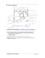
Page 22: ... is 19mm with or without video add on board measured from bottom of PCB to top of components including any underside components leads We recommend clearances of 5mm from bottom of PCB if mounting on a metal plate we also recommend a layer of suitable insulation material is added to the mounting plate surface 10mm above the components 3 5mm around the edges Any of the holes shown above can be used ...

Page 23: ...h the inverter specification see table CNB1 PIN DESCRIPTION 1 Ground 2 12V 24VDC Remark For higher power inverter more current for 12V 24V can be taken from CNA1 pin 1 Enable This is a pin provided on some inverters for On Off function and is used by this panel controller for VESA DPMS compliance If the inverter does not have an enable pin or the enable pin is not used then DPMS will not be operat...

Page 24: ...pends on the inverter The main power load for On Off is handled by a relay on the controller Example for circuit design Signal description Notes 1 R1 470ohm on board 2 RPOT is an external potentiometer in line dip style that can be plugged directly into CNC1 pins 3 4 5 RPOT must be supplied installed by user 3 BVR_B Voltage tapped from top of potentiometer the node of R1 and RPOT 4 BVR_WIP Voltage...

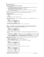
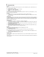
Page 25: ...ve any adverse effect Image appearance A faulty panel can have blank lines failed sections flickering or flashing display Incorrect graphics card refresh rate resolution or interlaced mode will probably cause the image to be the wrong size to scroll flicker badly or possibly even no image Incorrect jumper settings on the controller may cause everything from total failure to incorrect image CAUTION...

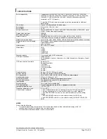
Page 26: ...functions Image controls Panel brightness contrast Saturation Hue Color temperature Sharpness Aspect ratio etc OSD menu controls available Power On Off Backlight brightness OSD Menu OSD Select up OSD Select down Setting Setting Control interface Buttons RS 232 IR Remote control Settings memory Settings are stored in non volatile memory PC Connectivity VGA SVGA XGA SXGA UXGA WUXGA analog or digital...

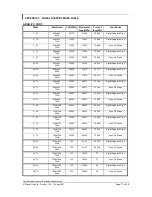
Page 27: ...2 800x600 72Hz 50 000 48 077 72 188 Digital Separate Sync SV_72 800x600 72Hz 50 000 48 077 72 188 Sync On Green SV_75 800x600 75Hz 49 500 46 875 75 000 Digital Separate Sync SV_75 800x600 75Hz 49 500 46 875 75 000 Sync On Green X_60 1024x768 60Hz 65 000 48 363 60 004 Digital Separate Sync X_60 1024x768 60Hz 65 000 48 363 60 004 Sync On Green X_70 1024x768 70Hz 75 000 56 476 70 069 Digital Separate...

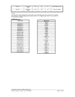
Page 28: ...higher refresh rate over 60Hz the LCD panel may not support HDMI input port Resolution 640x480 60Hz 640x480 72Hz 640x480 75Hz 800x600 56Hz 800x600 60Hz 800x600 72Hz 800x600 75Hz 1024x768 60Hz 1024x768 70Hz 1024x768 75Hz 1280x768 60Hz 1280x768 75Hz 1280x1024 60Hz 1280x1024 75Hz 1366x768 60Hz 1400x1050 60Hz 1440x900 60Hz 1600x900 60Hz 1600x1200 60Hz 1680x1050 60Hz 1920x1200 60Hz 2560x1600 60Hz Resol...

Page 29: ...40x900 60Hz 1600x900 60Hz 1600x1200 60Hz 1680x1050 60Hz 1920x1200 60Hz 2560x1600 60Hz SDI J4 port Mode 576i50 PAL 480i60 NTSC 720p60 4 2 2 720p59 94 4 2 2 720p50 4 2 2 1080p30 4 2 2 1080p29 97 4 2 2 1080p25 4 2 2 1080p24 4 2 2 1080p23 98 4 2 2 1080psf30 4 2 2 1080psf29 97 4 2 2 1080psf25 4 2 2 1080i60 4 2 2 1080i59 94 4 2 2 1080i50 4 2 2 1080p60 4 2 2 1080p59 94 4 2 2 1080p50 4 2 2 Resolution 720p...

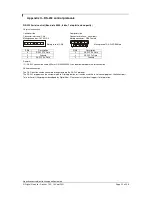
Page 30: ...N Description 4 RS 232 Tx Data 2 RS 232 Rx Data 5 Ground 3 RS 232 Tx Data 6 RS 232 Rx Data 5 Ground Remark 1 RS 232 connection cable 600mm P N 426090200 3 can be ordered separately for connection Software connection The OSD function can be controlled through sending the RS 232 protocol The RS 232 program can be custom made to fit for application or it can be used the serial control program like Ac...

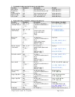
Page 31: ...ement Reset Query Current Source Maximum query 1 Minimum query 1 Brightness nn 0x00 0x64 0 100 Default 0x32 50 Contrast control all channels 0x82 a A nn r R m n Set all contrast value increment decrement Reset Query Maximum query 1 Minimum query 1 Contrast nn 0x00 0x64 0 100 Default 0x32 50 Saturation control 0x83 nn r R m n Set color value increment decrement Reset Query Maximum query 1 Minimum q...

Page 32: ...et it to the max available step Select OSD language 0x95 n r R Select language English Chinese Reset Query 0 English 2 French 3 Spanish Input main select 0x98 nn r R Select input main PC or VIDEO or next available Reset Query Main selected 0x41 0x31 ARGB 0x48 0x31 HDMI 1 0x48 0x32 HDMI 2 0x50 0x31 Display Port 0x45 0x31 HD SD SDI Auto Source Seek 0x99 nn 0 1 Set Auto source enable 1 Source Disable...

Page 33: ...x50 0x31 Display Port 0x45 0x31 HD SD SDI Colour temperature select 0xb3 n r R Select colour temperature value Reset Query Main selected 5 9300K 6 7500K Default 2 6500K 3 5000K 4 User Red level for selected colour temperature 0xb4 nn r R m n Set the level of the red channel for the selected colour temp value increment decrement Reset Query Maximum query Minimum query Red level for selected colour ...

Page 34: ... number Backlight control 0xe0 nn R r Set Backlight value increment decrement Display OSD indicator Reset Query Backlight nn 0x00 0x64 0 100 Default 0x64 100 Backlight On Off 0xe1 0 1 R r Backlight Off Backlight On Status 0 Backlight Off 1 Backlight On Default Backlight On Off Query Monochrome mode Output Channel Select 0xe2 0 1 2 3 4 5 6 R r Off Blue Only Red Only Green Only Blue Mono Red Mono Gr...

Page 35: ...cknowledge disabled 1 acknowledge enabled Auto setup 0xc3 Start auto setup of current vmode 0 fail 1 successful Command availability 0xc4 n Check whether a command is available 0 not available 1 available Soft Power On Off 0xc8 0 1 Soft power off on query 0 Soft power off 1 Soft power on Query video input status 0xc9 Query the status of the primary pip status nn nn input status nn xx digit primary...

Page 36: ... 0x1e is represented by 1 e E 0x31 0x6e 0x4e Please refer to the ASCII to Hex convert table below Hex to ASCII conversion table Hex ASCII Hex ASCII Hex ASCII Hex ASCII 0x30 0 0x41 A 0x61 a 0x2B 0x31 1 0x42 B 0x62 b 0x2D 0x32 2 0x43 C 0x63 c 0x3F 0x33 3 0x44 D 0x64 d 0x34 4 0x45 E 0x65 e 0x35 5 0x46 F 0x66 f 0x36 6 0x47 G 0x67 g 0x37 7 0x48 H 0x68 h 0x38 8 0x49 I 0x69 i 0x39 9 0x4A J 0x6A j 0x4B K ...

Page 37: ...Specifications subject to change without notice Digital View Ltd Doc Ver 1 00 10 Sept 2021 Page 37 of 46 Appendix III Mapping definition Definition of Mapping A Definition of Mapping B ...

Page 38: ...Specifications subject to change without notice Digital View Ltd Doc Ver 1 00 10 Sept 2021 Page 38 of 46 Definition of VESA ...

Page 39: ...Specifications subject to change without notice Digital View Ltd Doc Ver 1 00 10 Sept 2021 Page 39 of 46 Definition of JEIDA ...

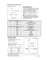
Page 40: ... then stored in the controller and are unaffected by the Reset Factory Defaults function This reference pattern is for 1280x1024 resolution and it needs to set your ARGB input source to 1280x1024 resolution before performing the Auto Color Gain function The position of the black vertical bar in the pattern at the right side is important It will affect the calibration result if you are setting the ...

Page 41: ... functions forward or increase the values BUTTON When OSD menu displayed press this button to select functions backward or decrease the values AV TV BUTTON Use to select the input source VGA DVI HDMI OSD NEXT BUTTON Use to turn on off the OSD menu Mute Mute Un mute audio STOP VGA BUTTON Press this button in the non OSD menu display mode to select VGA source DVI BUTTON Press this button in the non ...

Page 42: ... change without notice Digital View Ltd Doc Ver 1 00 10 Sept 2021 Page 42 of 46 Appendix VI PIP mix table PIP MAIN VGA CNV6 HDMI1 CN5 HDMI2 CN2 Displayport CN20 HD SDI J4 VGA CNV6 HDMI1 CN5 HDMI2 CN2 Displayport CN20 HD SDI J4 ...

Page 43: ...troller board Use of the light sensor board P N 416021310 3 and light sensor cable P N 426305900 3 connect to the HX 2560 SDI via CN6 connector as shown below Digital View provides a user friendly software program TCP IP Serial Utility V1 12 or later revision can set thresholds for ambient light and the LCD panel backlight adjustment When designing a monitor a light sensor can be placed in a suita...

Page 44: ...cts furnished hereunder including all implied warranties of merchantability and fitness for a particular application or purpose The stated express warranties are in lieu of all obligations or liabilities on the part of the manufacturer for damages including but not limited to special indirect consequential damages arising out of or in connection with the use of or performance of the products CAUTI...

Page 45: ...gan Hill California 95037 USA Tel 1 408 782 7773 Fax 1 408 782 7883 Sales ussales digitalview com EUROPE Digital View Ltd The Lake House Knebworth Park Herts SG3 6PY UK Tel 44 0 20 7631 2150 Fax Fax 44 0 20 7631 2156 Sales uksales digitalview com ASIA Digital View Ltd Unit 705 708 7 F Texwood Plaza 6 How Ming Street Kwun Tong Hong Kong Tel 852 2861 3615 Fax 852 2520 2987 Sales hksales digitalview ...

Page 46: ...Specifications subject to change without notice Digital View Ltd Doc Ver 1 00 10 Sept 2021 Page 46 of 46 Revision History Date Rev No Page Summary 10 Sept 2021 1 00 All First issued ...

Reviews: