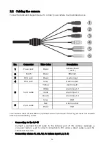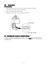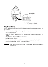
2.2 Cabling the camera
Follow the table and diagram below to connect your camera to all external devices.
No.
Connector
Wire Color
Description
1
Power jack
Black
Camera power
(12vdc)
2
RJ-45
Black
Ethernet
3
RCA jack
Black
Audio input
4
RCA jack
Gray
Audio output
5
5-pin cable
Yellow
Alarm input 1
White
Alarm input 2
Violet
Alarm input 3
Brown
Alarm input 4
Gray
GND
6
2-pin cable
Red
Alarm output
Black
GND
The camera must be installed by qualified service personnel following all local and federal
electrical and building codes.
• Connecting to the RJ-45
Connect a standard RJ-45 cable to the network port of the camera. Generally, a
crossover cable is used for direct connection to PC, while a direct cable is used for
connection to a hub.
• Connecting alarms A1, A2, A3, A4 (alarm input 1, 2, 3, 4)
8


