background image

Installation Step 3 

 Powering the WLN30 


Connect the 12/24v DC supply to RED (+) and BLACK (-) wires of the  
PWR/DATA cable. 


An in-line 1A fuse (not supplied) or suitable circuit breaker, should 
be wired in the positive power connection to protect the cabling.  


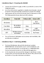
Apply power and the three LEDs should start to illuminate or flash. 
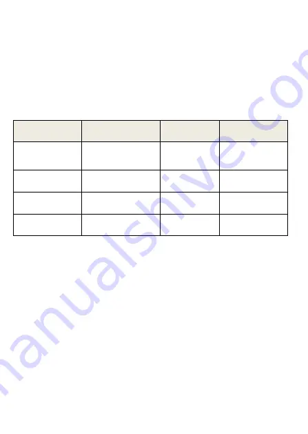
The following table shows what each LED indicates; 


Condition 

Red LED 

Yellow LED 

Green LED 

ON (Solid) 


TCP 

Connection 

Fast Blink 

No wireless 

connection 

Data 


Slow Blink 


Data 

UDP 

Connection 

OFF 

Wireless device 

connected 

No Data 

No Power 


Turn off the Smart Multiplexer and continue with the NMEA, USB 
and Wireless installation.   
   

Installation Step 4 

 Interfacing (NMEA) 


The Smart Multiplexer allows full bi-directional, wireless 
NMEA0183 data communication, but in some installations, you 
only need communication in one direction i.e. NMEA0183 data 
from an instrument system to an iPhone/iPad application.  


In this situation do not connect the Orange (+) and Brown (-) data 
output wires, just trim the bare ends and ensure they cannot touch 
each other or any other electrical connections. 


Summary of Contents for WLN30

Page 1: ...WLN30 SMART WIRELESS NMEA MULTIPLEXER Version 1 01...

Page 2: ...unit you should consult the user manual of the navigation equipment that you are connecting this unit to 2 Before you start You will need the following items and tools to complete the installation The...

Page 3: ...cable connections Maintaining the compass safe distance of 0 5m Best location for Wi Fi reception i e not inside a metal enclosure Installation Step 1 Cabling Run 12v or 24v power connections to the S...

Page 4: ...No wireless connection Data Slow Blink Data UDP Connection OFF Wireless device connected No Data No Power Turn off the Smart Multiplexer and continue with the NMEA USB and Wireless installation Insta...

Page 5: ...Smart Multiplexer Port 1 is set to 38400 baud while Port 2 and 3 are set to 4800 baud but they can all be changed via the WLN30 s built in web interface Installation Step 5 Wireless Interfacing By def...

Page 6: ...on that accepts NMEA data over a TCP or UDP connection and setup the connection Consult the help documentation for your App to see how wireless data connections should be configured The Smart Multiple...

Page 7: ...er devices Alternatively if the boat already has a Wireless Router onboard you can make the Smart Multiplexer connect to that network rather than create its own Select Station mode in the Smart Web In...

Page 8: ...et Port 1 NMEA Output to output the Multiplexed data 38400 or Wireless App data 4800 3 Firmware Update The firmware of the Smart Multiplexer can be updated using web interface simply click the Choose...

Reviews: