background image


Overload protection: 0.5A/250V, 10A/250V fuse. 

[1] 10A for 15sec each 15min maximum. 


2.2.4 AC Current (

AC+DC True RMS

)

 [1]


Range 

Accuracy    ± ([% of Reading] + [Counts]) 


DC, 45Hz to 2kHz 

400µA, 4000µA 

2.0%+3 

40mA, 400mA 

2.0%+3 

4A,10A

[2]


2.5%+3 

Overload protection: 0.5A/250V, 10A/250V fuse. 

[1] All ac ranges are specified from 1 % to 100 % of range. Below 5 % of range, add10 counts. 
Because inputs below 1 % of range are not specified, it is normal for this and other true-rms 
meters to display nonzero readings when the test leads are disconnected from a circuit or are 
shorted together. For volts and amps, crest factor of ≤3 at 3000 counts, decreasing linearly to 2 at 
full scale.    AC volts and AC amps are dc-coupled. 

[2] 10A for 15sec each 15min maximum. 


2.2.5 Resistance 

Overload protection: 250V DC or AC rms


2.2.6 Capacitance 

Overload protection: 250V DC or AC rms 

 
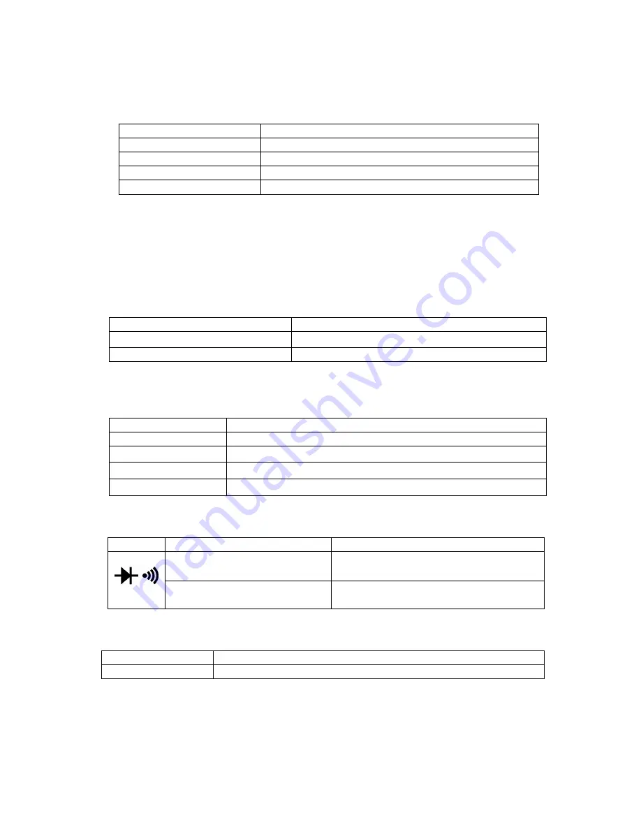
2.2.7 Diode and Audible continuity test 

Range 

Description 

Test condition 

Display    read approximately 
forward voltage of diode 

Forward DC current approx. 0.4mA

.


Reversed DC voltage approx. 2.8V 


Built-in buzzer sounds if 
resistance is less than 100Ω 

Open circuit voltage 
approx. 0.5V 

Overload protection: 250V DC or AC rms 

 
2.2.8 Frequency 

Range 

Accuracy    ± ([% of Reading] + [Counts]) 

10Hz~10MHz 

± ( 0.1%+5 ) 

Sensitivity: sine wave 0.6V rms (10MHz: 1.5V rms) 
Overload protection: 250V DC or AC rms 

 
2.2.9 Duty cycle 

0.1%

99.9%: ± ( 2.0%+2 )    Frequency lower than 10kHz 

Sensitivity: sine wave 0.6V rms 
Overload protection: 250V DC or AC rms 

Range 

Accuracy    ± ([% of Reading] + [Counts]) 

400Ω,4kΩ,40kΩ, 400KΩ

4MΩ 

1.0%+2 

40MΩ 

2.0%+3 

Range 

Accuracy    ± ([% of Reading] + [Counts]) 

40nF 

± ( 3.0%+10 ) 

  400nF

4µF 

± ( 2.5%+5 ) 

40µF 

± ( 5.0%+10 ) 

400µF

4000µF 

± ( 20.0%+20) 

Summary of Contents for DT-2844R

Page 1: ...4 4 4000 COUNTS AUTO 000 COUNTS AUTO 000 COUNTS AUTO 000 COUNTS AUTO RANGE RANGE RANGE RANGE AC DC TRUE AC DC TRUE AC DC TRUE AC DC TRUE RMS RMS RMS RMS DIGITAL MULTIMETER DIGITAL MULTIMETER DIGITAL...

Page 2: ...Do not operate the meter if the body of meter or the test lead look broken 1 2 Check the main function dial and make sure it is at the correct position before each measurement 1 3 When making current...

Page 3: ...ICATIONS Accuracies are of reading number in last digit at 23 5 C 75 RH 2 2 1 DC Voltage Overload protection 600V DC or AC rms Impedance 10M More than 100M on 400mV range 2 2 2 AC Voltage AC DC True R...

Page 4: ...c each 15min maximum 2 2 5 Resistance Overload protection 250V DC or AC rms 2 2 6 Capacitance Overload protection 250V DC or AC rms 2 2 7 Diode and Audible continuity test Range Description Test condi...

Page 5: ...r duty cycle 3 4 Resistance Measurement 1 Connect the black test lead to COM socket and red test lead to the V Hz socket 2 Set the selector switch to desired position 3 Press SELECT key to choose Resi...

Page 6: ...s non effective on Hz DUTY measurement It can not display bar graph on Relative measurement mode 3 11 Auto Manual range The auto range mode is a convenient function but it might be faster to manually...

Page 7: ...bottom case and fasten the screws then close the battery cabinet cover and fasten the screw 6 MAINTENANCE 1 Before open the battery cover disconnect both test lead and never uses the meter before the...

Reviews: