Model: db BioLock, db ELock, db iCardLock
Digitus Biometrics, Inc. 2014
Page 10 of 11
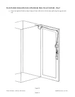
Connect the cable to the Remote Node / Zero-U Controller – Step 8
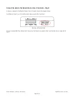
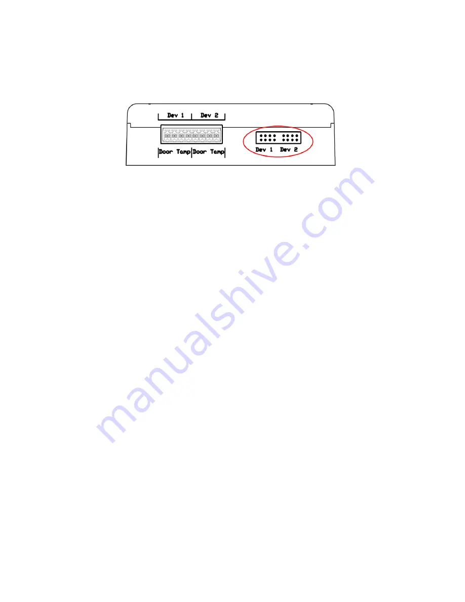
Locks are connected to the Remote Node or Zero-U’s socket circled in the diagram below.
Each Remote Node / Zero-U Controller has two device inputs, Dev 1 and Dev 2.
Side View of Remote Node
It is recommended that for a cabinet with 2 doors, the front door is connected to Dev 1 and the back door is connected to
Dev 2.


