background image


DIGITUS

®

 Professional OnLine 

1000-3000 VA UPS System 


User Manual


DN-170089 

DN-170090 

DN-170091 

DN-170092


Summary of Contents for DN-170089

Page 1: ...DIGITUS Professional OnLine 1000 3000 VA UPS System User Manual DN 170089 DN 170090 DN 170091 DN 170092...

Page 2: ...is symbol indicates that you should not discard the UPS or the UPS batteries in the trash This product contains sealed lead acid batteries and must be disposed of properly For more information contact...

Page 3: ...Table of Contents 1 Introduction 4 2 Safety Warnings 5 3 Installation 5 4 Operation 15 6 UPS Maintenance 35 7 Specifications 39 8 Troubleshooting 43...

Page 4: ...table High Efficiency mode of operation Cold start function to startup the UPS without utility Standard communication options one RS 232 communication port one USB communication port and relay output...

Page 5: ...current protection in accordance with the National Electrical Code NEC ANSI NFPA 70 Output overcurrent protection and disconnect switch must be provided by others To comply with international standard...

Page 6: ...onents packaged until ready to install To unpack the cabinet and accessories 1 Open the outer carton and remove the accessories packaged with the cabinet 2 Carefully lift the cabinet out of the outer...

Page 7: ...Rail hardware kit 8 M5butterfly nuts 2 rear stop brackets 8 M5 umbrella nuts Mounting bracket kit 2 mounting brackets 8 M4_8 flat head screws Tools Required To assemble the components the following to...

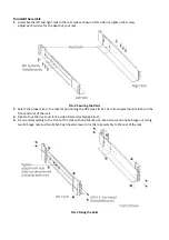
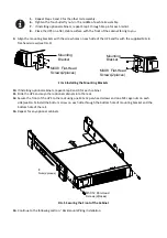
Page 8: ...er size in the rack for positioning the UPS see FIG 3 The rail occupies four positions on the front and rear of the rack 3 Tighten four M5 rivet nuts in the side of rail assembly see FIG 2 4 Fix one r...

Page 9: ...10 If installing optional cabinets repeat Step 8 and 9 for each cabinet 11 Slide the UPS and any other optional cabinets into the rack 12 Secure the front of the UPS to the rack using one M5 12 pan h...

Page 10: ...ke unauthorized changes to the UPS otherwise damage may occur to your equipment and void your warranty NOTE Do not connect the UPS power cord to utility until after installation is completed To instal...

Page 11: ...eries or adding the internal batteries The plug will be connected properly if the UPS is with batteries installed CAUTION A small amount of arcing may occur when connecting the internal batteries This...

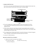
Page 12: ...or bonding of ungroundedmetal parts connect the ground cable not supplied to the groundbonding screw See Rear Covers for the location ofthe ground bonding screw for each model 6 If an emergency power...

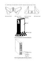
Page 13: ...Fig 11 shows FIG 10 plastic base installation FIG 11 The installation for UPS and battery box FIG 12 Long backup external battery connection UPS Plastic base Plastic base bracket Battery Plastic base...

Page 14: ...ck the UPS front cover display for active alarms or notices Resolve any active alarms before continuing See Troubleshooting Table 23 Typical alarm conditions If the indicator is on do not proceed unti...

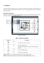
Page 15: ...rements and settings see FIG 13 FIG 13 Control Cover Table 1 Indicator Descriptions Indicator Description Red On The UPS has an active alarm or fault Yellow On The UPS is in Bypass mode The UPS is ope...

Page 16: ...and hold the key for more than half a second less than 2 seconds Indicate the items of the LCD item section orderly Press and hold this key for more than 2 seconds Circularly and orderly display the i...

Page 17: ...second 3 Bypass mode Main AC Normal voltage in bypass mode Once every two minutes Eliminate after starting the UPS Main AC high voltage warning in bypass mode Once every four seconds Main AC low volt...

Page 18: ...y 2 seconds Check if the fan is blocked by object 8 Fault mode Long beeps If display fault code and icon lights contact for maintenance when you can t deal with it by yourself _indicator lights for a...

Page 19: ...dynamic fan blades rotating when the fan works abnormally the icon will keep on flashing with the warning Charger status graphics section Display the status of the charger When charger works normally...

Page 20: ...Display the temperature of the inverter in the UPS Asthe following graphics shown the temperature of the inverter is 37 C Input Display the voltage and frequency of the input As the following graphic...

Page 21: ...h The ON or OFF below the ECO will flash Press and hold the scroll key for more than half a second less than 2 seconds to determine whether the ECO function is enabled or disabled Confirm the ECO sele...

Page 22: ...t press the scroll key or for more than half a second shorter than 2 seconds to select the voltage range in percentage 5 10 15 25 default is 25 then short press function setting key for more than half...

Page 23: ...s than 2 seconds select the function setting choose battery setting interface at the moment the letters bAt will flash Enter the battery setting interface Press and hold the function setting key for m...

Page 24: ...Press and hold function setting key for more than half a second less than 2 seconds exit from the setting interface and return to main interface Automatic Battery Test mode setting 6 Enter the settin...

Page 25: ...lf a second less than 2 seconds then come to setting interface of wc at this time the letters Abt will light for a long time The ON or OFF below the Abt will flash Press and hold the inquiring key for...

Page 26: ...than half a second less than 2 seconds Now the setting is confirmed Exit from the setting interface Press and hold function setting key for more than half a second less than 2 seconds exit from the s...

Page 27: ...less than 2 seconds select the output frequency 50Hz output fixed to 50Hz and active converter mode or 60Hz output fixed to 60Hz and active converter mode or IPF inactive converter mode and active nor...

Page 28: ...can be set by LCD Under below conditions the UPS will transfer to bypass mode BPS on set by user through LCD and the UPS is turned off BPS on set by user through LCD and the UPS is plugged into utili...

Page 29: ...LED lights and the UPS are working in battery mode Turn off operation Turn off the UPS in line mode 1 Press and hold the OFF key for more than half a second to turn off the UPS and inverter 2 After th...

Page 30: ...232 and USB Connectivity cards Emergency Power off EPO Load Segments Digitus Professional Management Software FIG 14 DN 170089 1000VA DN 170090 1500VA Rear Cover FIG 15 DN 170092 2000VA Rear Cover BR...

Page 31: ...peed of the RS232 port is fixed at 2400 bps RS 232 and USB Communication Ports To establish communication between the UPS and a computer connect your computer to one of the UPS communication ports usi...

Page 32: ...icate in a variety of networking environments and with different types of devices The UPS has one available communication bay for the following connectivity cards Web SNMP Card has SNMP and HTTP capab...

Page 33: ...is an IEC 60950 safety extra low voltage SELV circuit This circuit must be separated from any hazardous voltage circuits by reinforced insulation CAUTION The EPO must not be connected to any utility...

Page 34: ...test the EPO function before applying your critical load to avoid accidental load loss Load Segments Load segments are sets of receptacles that can be controlled by power management software or throug...

Page 35: ...batteries Recycle used batteries or UPS UPS and Battery Care For the best preventive maintenance keep the area around the UPS clean and dust free If the atmosphere is very dusty clean the outside of...

Page 36: ...not lay tools or metal parts on top of batteries 4 Wear rubber gloves and boots When replacing batteries replace with the same type and number of batteries or battery packs Contact your service repre...

Page 37: ...FIG 21 TheInstallation for baffle of battery pack M3X6 Sunk Head Screws 2places M3X6 Pan Head Screw 5places Insert the thin wall into the slot M3X6 Sunk Head Screws 2places M3X6 Pan Head Screw 1places...

Page 38: ...ure it is completely inserted into the chassis as fig 23 shown FIG 23 Installation for battery pack Testing New Batteries To test new batteries 1 Plug the UPS into a power outlet for 48 hours to charg...

Page 39: ...ry or batteries Released electrolyte is harmful to the skin and eyes It may be toxic CAUTION Do not discard the UPS or the UPS batteries in the trash This product contains sealed lead acid batteries a...

Page 40: ...0 60 Hz auto sensing Frequency Range 45 55 Hz 50Hz 55 65Hz 60Hz before transfer to battery Bypass Voltage Range 5 10 15 25 25 by default 20 30 45 45 by default Table 12 Electrical Input All Models Mod...

Page 41: ...put Overload Bypass Mode 100 5 130 5 Load transfers to Fault mode after 20 minutes 130 5 150 5 Load transfers to Fault mode after 2 minutes 150 5 200 5 Load transfers to Fault mode after 15 seconds 20...

Page 42: ...hes load to Bypass in case of overheating Storage Temperature 20 C to 40 C 4 F to 104 F with batteries 25 C to 55 C 13 F to 131 F without batteries Transit Temperature 25 C to 55 C 13 F to 131 F Relat...

Page 43: ...ilure detection and warning Recharge Time to 90 8 hours to 90 8 Troubleshooting The following messages are the information that users would find on UPS when it meets some problems Users can judge if t...

Page 44: ...ith mains power for more than 8 hours recharge battery UPS overload Check the usage of loads remove some redundant devices Battery aged When replace battery contact franchiser to get battery and relat...

Page 45: ...rload 03 09 45 Fan Fault 36 28 38 46 Charge Fault 07 07 Bat Over 11 11 11 11 This is a Class A product In home environment this product may cause radio interference In this case the user may be requir...

Reviews: