3.
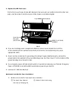
Replace the UPS front cover.
Put the front cover hooks of side with display to the cover port, put another side to the other two
ports, and then press it until the cover and the chassis are combined tightly.
FIG. 9
4.
If you are installing power management software, connect yourcomputer to one of the
communication ports or optional connectivity card. For the communication ports, usean
appropriate cable.
5.
If your rack has conductors for grounding or bonding of ungroundedmetal parts, connect the
ground cable (not supplied) to the groundbonding screw. See “Rear Covers” for the location ofthe
ground bonding screw for each model.
6.
If an emergency power-off (disconnect) switch is required by localcodes, see “Remote Emergency
Power-off” (REPO) to install the REPO switch before powering on the UPS.
7.
Continue to “UPS Initial Startup”.
Rackmount converted to Tower Installation
1.
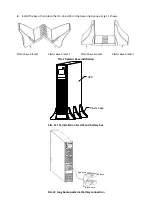
Rackmount converted to Tower plastic base installation
①
Two plastic base brackets
intercross as following FIG.
②
Flatten it after intercrossing
EBM
Cover Hooks
(2places)
Insert the two
thin-wall
into the slot.
Top
EBM Cable Knockout


