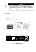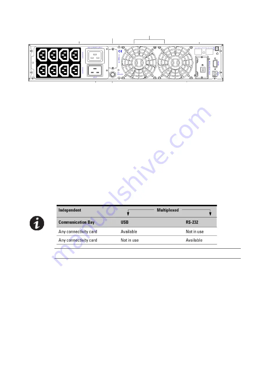
FIG. 16 DN-170091 (3000VA) Rear Cover
Installing Communication Options and Control Terminals
To install the communication options and control terminals:
1.
Install the appropriate connectivity card and/or necessary cable(s) and connect the cables
to the appropriate location.
2.
Route and tie the cable(s) out of the way.
3.
Continue to
4.
Operationto start up the UPS.
Communication Options
The UPS has serial communication capabilities through the USB and RS-232 communication
ports or through a connectivity card in the available communication bay. The UPS supports two
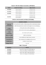
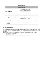
serial communication devices according to the following table:
NOTE:
The communication speed of the RS232 port is fixed at 2400 bps.
RS-232 and USB Communication Ports
To establish communication between the UPS and a computer, connect your computer to one
of the UPS communication ports using an appropriate communication cable (not supplied).
See FIG.14 -16 for the communication port locations.
When the communication cable is installed, power management software can exchange data
with the UPS. The software polls the UPS for detailed information on the status of the power
environment. If a power emergency occurs, the software initiates the saving of all data and an
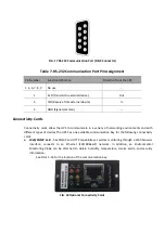
orderly shutdown of the equipment. The cable pins for the RS-232 communication port are
identified in FIG.17 and the pin functions are described in Table 8.
OUTPUT SCOCKET
BATTERY SCOCKET
FAN
NET SURGE
PROTECT
(optional) EPO
RS232, USB
AC INPUT
INPUT
BREAKER
INTERNAL SNMP SLOT


