background image

INTRODUCTION 

This rugged designed Industrial Gigabit 4 port POE Switch, which 
comply with IEEE802.3af and IEEE802.3at, has pass many rigorous 
environmental test. It delivers 30watts power per POE portand can 
generate total 120 watts power to PD devices. The 2 uplink SFP ports 
can extend your environment to a much larger area. 
 
The wide range model can cover 12/24/48VDC input to boost voltage to 
55VDC. It guaranty to meet IEE802.3at and to delivery full POE power 
up to 30Watts per POE port to a PD. With its multi-purpose design, it can 
also be used for Din-Rail or wall-mounted. It is an ideal unit for IP 
surveillance, traffic monitoring and Security application in critical 
environment. It can tolerate -40°C to 75°C in harsh environment to 
perform a reliable network. 
 

  Super Voltage Booster 12/24/48 VDC Industrial Gigabit 4 port POE+ 

Switch  


Summary of Contents for DN-651103

Page 1: ...Industrial 10 100 1000M Ethernet Switch with PoE Manual DN 651103 ...

Page 2: ...r area The wide range model can cover 12 24 48VDC input to boost voltage to 55VDC It guaranty to meet IEE802 3at and to delivery full POE power up to 30Watts per POE port to a PD With its multi purpose design it can also be used for Din Rail or wall mounted It is an ideal unit for IP surveillance traffic monitoring and Security application in critical environment It can tolerate 40 C to 75 C in ha...

Page 3: ...DIMENSIONS OF THE HOUSING Front view Side view Back view Top view Bottom view ...

Page 4: ... m It accep C And it is redundanc applicatio on and Te PACKA lled by din unted bra abit 4 por The high p gh efficien such as equiremen tage also pts the inp s also equ cy cascad on It is be elco applic AGE n rail mou cket are i rt POE Sw power 4 po cy ColdD 12 24 48V nt The Co o reduce t put voltag uipped wit ded to you eing rigoro cation unted or w ncluded D 6 witch ort industr esign tech VDC be ...

Page 5: ...elay You may use 24V 1A relay connection to your external device for special purpose When 2 powers are connected the relay is in SHORT mode When any power source fails the relay change it s in OPEN status POWER CONNECTING PROCEDURE STEP 1 Pull out 6 pin terminal block STEP 2 Connect wire to V1 V1 or V2 V2 and Ground the neutral wire to the ground screw STEP 3 Plug back 6 pin terminal block to its ...

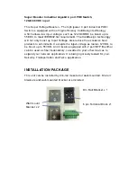
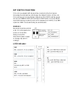
Page 6: ... 5 as TX disable port 5 SFP or set SFP speed to 100M The detail setting as shown below WARNING Dip switch function will not work if it is changed when power is connected Always turn off or disconnect power supply to change dip switch settings LED indicator PW1 ON when V1 V1 is connected F6 ON port 6 SFP fiber is detected OFF port 6 SFP fiber is not LNK ON TX link is detected OFF TX port is not det...

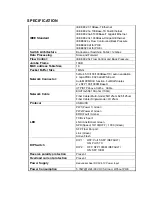
Page 7: ... X auto negotiation 4 Giga POE 802 3at af PSE port Auto MDI MDI X function Full Half duplex 2 x SFP 100 1000M BaseX Network Cable UTP STP above Cat 5e Cable EIA TIA 568 100 ohm 100m Fiber Cable Multi mode 50 125um 62 5 125um Fiber Cable Single mode 9 125um Protocol CSMA CD LED PW1 Power 1 Green PW2 Power 2 Green ERR Fault Amber TX RJ 45 port LNK Link Active Green SPD Speed 10 100 OFF 1000 Green SF...

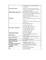
Page 8: ...wer input Removable Terminal Block Provide 2 Redundant power Alarm relay contact 6 Pin Wire range 0 34mm 2 to 2 5mm 2 Solid wire AWG 12 24 14 22 Stranded wire AWG 12 24 14 22 Torque 5lb In 0 5Nm 0 56Nm Wire Strip length 7 8mm Operating Temperature 40 75 fully tested POE efficiency Voltage boost efficiency up to 97 from 12VDC to 55VDC Surface temperature Surface temperature rises 6 C full load in a...

Reviews: