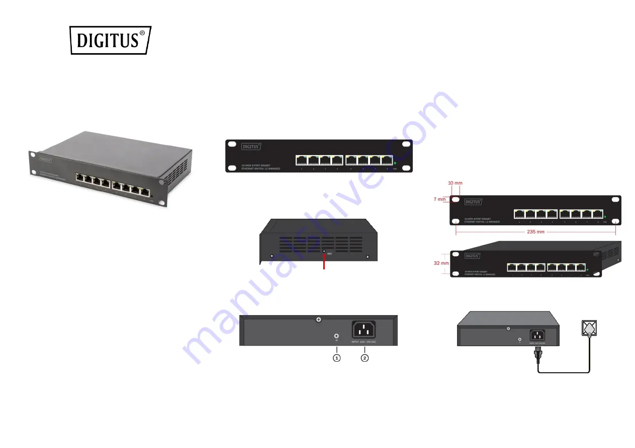
10-INCH 8-PORT GIGABIT
ETHERNET SWITCH, L2 MANAGED
Quick installation guide
DN-80117
1.
About Guide
This guide provides instructions to install the Ethernet Switch.
Note:
The model you have purchased may appear slightly different from the
illustrations shown in the document. Refer to the Product Instruction and
Technical Specification sections for detailed information about your switch, its
components, network connections, and technical specifications.
This guide mainly divided into 4 parts:
1. About guide: Terminology/Usage
2. Product introduction: functional overview and introduction of panel definitions
3. Hardware installation: step by step hardware installation process
4. Technical Specifications
Terminology / Usage
In this guide, the term "Switch" (first letter capitalized) refers to the Ethernet Switch,
and "switch" (first letter lower case) refers to other Ethernet switches. Some
technologies refer to terms "switch", "bridge" and "switching hubs" interchangeably,
and both are commonly accepted for Ethernet switches.
Note:
indicates important information that helps a better use of the device.
Warning:
indicates potential property damage or personal injury.
Copyright and trademark
The pictures and data shown in this guide are for reference only, subject to change
without notice.
2.
Products Introduction
Thanks for purchasing the Managed Ethernet switch products
.
This product is a network management type Gigabit Ethernet Switch. The machine
comes with 8x 10/100/1000 Mbps RJ45 ports which can satisfy the full speed
forwarding of ports. The machine is a small size metal-shell device which is useful for
the small office can home and the IP solution project using, be used on the desktop or
Wall mounting. Excellent performance can help you widely use in wireless, monitoring
and other fields.
Front Panel
The front panel consists of LED indications and network ports
LED Lamp
Power LED:
The Power LED lights up when the switch is connected to a power source.
Link/Act indicator:
the light indicates the network connection through the
corresponding port. Flicker indicates that the switch is sending or receiving data.
Side Panel
RST:
By pressing the Reset button for 5 seconds the switch will change back to the
default configuration and all changes will be lost.
Rear Panel
The rear panel view of the Ethernet switch consists of an AC power connector.
(1)
Grounding:
use specialized ground lead connect
(2)
Connect the power adapter output terminal to this port.
Supports input voltages 100-240VAC
3.
Hardware installation
This chapter provides unpacking and installation information for the Managed
Ethernet Switch.
Open a seal
Open the shipping carton and carefully unpack its contents. Please consult the packing
list located in the User Manual to make sure all items are present and undamaged. If
any item is missing or damaged, please contact the local reseller for replacement.
Switch 1pcs
User's manual 1pcs
AC power cord 1pcs
CD ROMs 1pcs
Switch installation
For safe switch installation and operation, it is recommended that you:
Visually inspect the power cord to see that it is secured fully to the AC power
connector.
Make sure that there is proper heat dissipation and adequate ventilation around
the switch.
Do not place heavy objects on the switch.
Installation hole spacing
Connecting power supply
Using the AC power cord to connect to of the into the AC socket on the back of the
switch.
Warning:
Do not turn on the power switch before power cables are connected.
Power surge may cause damage to the Switch.
Power failure
As a precaution, the switch should be unplugged in case of power failure. When power
is resumed, plug the switch back in.


