background image


  DIGITUS POE Web Smart Ethernet Switch 


24

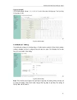
4.6.2 Port, 802.1p, IP/DS based   

There are three COS types for this setting. The user can select more than one item for each 
port. 


As long as any of three CoS schemes(802.1p, IP TOS/DS or Port Base) is mapped to "high", 
the data packet will be treated as the high priority.   

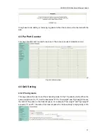
4.6.3 TCP/UDP Port Based   

This page allows the network administrator to assign the specific application to a priotity 
queue. When the TCP/UDP port QoS function "override" item is selected, the Port_based, 
Tag_based, IP TOS_based, CoS listed above will be ignored.   


4.7 Security 

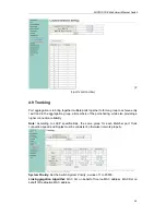
4.7.1 MAC Address Binding 

This is a port binding feature. This function provides a method for the administrator to 
specify the relationship between the physical port and the MAC address. By specifying the 
MAC address to each port, the switch can only forward the packets with source specified in 

Summary of Contents for DN-95312

Page 1: ...16 PORT 10 100MBPS PoE WEB SMART ETHERNET SWITCH 24 PORT 10 100MBPS 2G COMBO PoE WEB SMART ETHERNET SWITCH Manual DN 95312 DN 95313 ...

Page 2: ...nnect Computer NIC to the Switch 10 2 3 Switch connection to the PD 10 Chapter 3 How to Login the Switch 11 3 1 Switch to End Node 11 3 2 How to Login the Switch 11 Chapter 4 Switch Configuration 13 4 1 Administrator 13 4 1 1 Authentication configuration 13 4 1 2 System IP Configuration 13 4 1 3 System status 13 4 1 4 Load default setting 14 4 1 5 Firmware update 14 4 1 6 Reboot device 15 4 2 POE ...

Page 3: ... Port Based 24 4 7 Security 24 4 7 1 MAC Address Binding 24 4 7 2 TCP UDP Filter 25 4 8 Spanning Tree 26 4 8 1 STP Bridge Settings 26 4 8 2 STP Port Settings 26 4 8 3 Loopback Detection 27 4 9 Trunking 28 4 10 DHCP Relay Agent 29 4 10 1 DHCP Relay Agent 29 4 10 2 Relay Server 29 4 10 3 VLAN MAP Relay Agent 29 4 11 Backup Recovery 29 4 12 Miscellaneous 30 4 13 SNMP Settings 31 4 14 Logout 31 Append...

Page 4: ...IP Cameras or IP Phones etc The Switch may carry on the management and the condition monitoring through the network management software to the POE power supply function may demand opens or the closure port POE power supply function willfully provides the port power supply priority management the 10 100M POE Switch is a great selection for expanding your home or office network 1 2 Features 1 16 24p...

Page 5: ...P port and an associated RJ45 port are referred to as Combo port which means they cannot be used simultaneously and only SFP port work or only RJ45 port work at the same time Reset Keep the device powered on and push a paper clip into the hole Press down the button for about 2 seconds The system restores the factory default settings 1 3 2 Rear Panel The rear panel of the Switch contains AC power c...

Page 6: ...NK ACT 1 24 Green On A device is connected to the port Off A device is disconnected to the port Flashing Sending or receiving data 25 26T S LINK ACT Green On A device is connected to the port Off A device is disconnected to the port Flashing Sending or receiving data Speed Green On A 1000Mbps device is connected to the port Off A 10Mbps device is connected to the port Flashing A 100Mbps device is ...

Page 7: ...ce powered on and push a paper clip into the hole Press down the button for about 2 seconds The system restores the factory default settings 1 3 5 Rear Panel The rear panel of the Switch contains AC power connector shown as below Figure 2 Rear Panel AC Power Connector Power is supplied through an external AC power adapter It supports AC 100 240V 50 60Hz Grounding Terminal The Switch already comes ...

Page 8: ...INK ACT 1 16 Green On A device is connected to the port Off A device is disconnected to the port Flashing Sending or receiving data POE Orange On A Powered Device is connected to the port which supply power successfully Off No Powered Device connected to the port or no power is supplied according to the power limits of the port Flashing The POE power circuit may be in short or the power current ma...

Page 9: ...is proper heat dissipation from and adequate ventilation around the Switch Make sure the cabinet to enough back up the weight of the Switch and its accessories 2 1 1 Desktop Installation Sometimes users are not equipped with the 19 inch standard cabinet So when installing the Switch on a desktop please attach these cushioning rubber feet provided on the bottom at each corner of the Switch in case ...

Page 10: ...se follow the next tips to connect AC Electrical Outlet It is recommended to use single phase three wire receptacle with neutral outlet or multifunctional computer professional receptacle Please make sure to connect the metal ground connector to the grounding source on the outlet AC Power Cord Connection Connect the AC power connector in the back panel of the Switch to external receptacle with the...

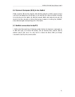
Page 11: ...ce between Switch and computer is around 100 meters Once the connection is OK and the devices are power on normally the LINK ACT status indicator lights corresponding ports of the Switch 2 3 Switch connection to the PD 1 16 24 ports of the Switch have POE power supply function the maximum output power up to 30W each port it can make PD devices such as internet phone network camera wireless access ...

Page 12: ...itch provides Web based management login you can configure your computer s IP address manually to log on to the Switch The default settings of the Switch are shown below Parameter Default Value Default IP address 192 168 2 1 Default user name admin Default password admin You can log on to the configuration window of the Switch through following steps 1 Connect the Switch with the computer NIC inte...

Page 13: ...actory default login ID is admin and Password is admin and then click OK to log in to the Switch configuration window as below 24 port version view In the Web GUI the left column shows the configuration menu and the rest of the screen area displays the configuration settings ...

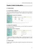
Page 14: ...ess Update button to take effect 4 1 2 System IP Configuration This page shows system configuration including the current IP Address and Subnet Mask Gateway and IP Configure IP Address Subnet Mask and Gateway at system IP Configuration diagram box can be configured by user The Switch also supports DHCP methods to get IP address from DHCP server 4 1 3 System status This page is used to check the st...

Page 15: ...ng page and then the process of the load default setting will be executed Press Reboot button to take effect After completing load default procedure IP address user name and password will keep original setting 4 1 5 Firmware update After pressing Update button the Switch will erase the older version flash code first Then enter file name at specific path and the update will be completed Using defau...

Page 16: ...DIGITUS POE Web Smart Ethernet Switch 15 4 1 6 Reboot device This page is used to reboot device Press Confirm button to take effect for rebooting device ...

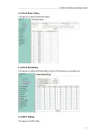
Page 17: ...ch 16 4 2 POE 4 2 1 POE Status This page is used to check POE Status you can set Max Available Power here 4 2 2 POE Setting This page is for PoE setting Status Enable or disable the specified function Priority Setting the priority of POE ...

Page 18: ...rnet Switch 17 4 2 3 PoE Power Delay This page is for setting PoE Power Delay 4 2 4 PoE Scheduling This page is for setting PoE Scheduling it starts POE function at a specified time 4 2 5 NTP Setting This page is for NTP setting ...

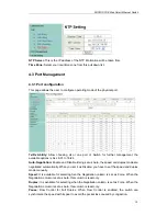
Page 19: ...ation Enable and Disable Being set as Auto the speed and duplex mode are negotiated automatically When you set it as Disable you have to set the speed and duplex mode manually Speed It is available for selecting hen the Negotiation column is set as Force When the Negotiation column is set as Auto this column is read only Duplex It is available for selecting when the Negotiation column is set as Fo...

Page 20: ... items a Destination port Theoretically it s possible to set more than one destination port in a network Actually the port mirroring function will lower the network throughput and therefore it s recommended to set only one destination port in a network b Monitored packets 1 Disable means this function is disabled 2 RX means copy the incoming packets of the selected source port to the selected dest...

Page 21: ...ed and threshold is set to 10 The broadcast packets will be dropped when broadcast packets are more than threshold setting packet length is 64 bytes 2 4 port version view 4 4 VLAN Setting 4 4 1 VLAN mode The Switch supports two VLAN modes tag based and port based When the port based VLAN is selected the tag setting will be useless When the tag based VLAN is selected the user can define the handlin...

Page 22: ...packets of the output will be stripped tag if remove tag option is selected Don t care means the egress packets of the output port only forward to destination without adding or removing tag 4 4 2 VLAN Member Setting This page is used to set the VLAN ID The VLAN ID is valid only when the tag based VLAN is enabled In port based VLAN mode the VLAN ID is useless Port based VLAN Port1 3 is set to same ...

Page 23: ... exclusive to VLAN setting on VLAN member setting When VLAN member setting is updated multi to 1 setting will be void and vice versa The Disable Port means the port is excluded in this setting 2 4 port version view Note If the VLAN mode changes from port base to tag base the setting of the port base will be cleared Similarly if the VLAN mode changes from tag base to port base the setting of the ta...

Page 24: ...tics in total 2 4 port version view 4 6 QoS Setting 4 6 1 Priority mode This page allows the user to set the scheduling mode for the TX packets priority When the queue weight is set to 0 it will be treated as 8 The low weight and high weight means the ratio of the packet in the transmit queue For example If low weight and high weight are set to 3 and 5 the ratio of the transmit packet for the low ...

Page 25: ...is page allows the network administrator to assign the specific application to a priotity queue When the TCP UDP port QoS function override item is selected the Port_based Tag_based IP TOS_based CoS listed above will be ignored 4 7 Security 4 7 1 MAC Address Binding This is a port binding feature This function provides a method for the administrator to specify the relationship between the physical...

Page 26: ...her protocols The negative list makes the switch drop the selected protocol and forward other protocol The protocol is checked at the selected secure WAN port The Switch supports two methods to filter TCP UDP protocol Allow means that when the port number of the selected port matches the port number of the filter setting the packets will be forwarded to destination port Deny means that when the po...

Page 27: ...transfer RSTP STP improved algorithm within the agreement time to 1s 4 8 2 STP Port Settings This feature is available to you to switch the priority of each port and RPC set usually set according to the following priority rules and RPC can remain the default RPC Root Path Cost The value range is 0 200000000 used to determine the port to the root path cost often with the speed so when set to Auto i...

Page 28: ...when the switch will automatically block out the port connecting to ensure other ports work When you set the Auto Wake Up and Wake Up Time Interval option and the network loop appears when the intervals the switch port will wake up trying to loop until the fault discharged Reset All Ports This button provides a key to force you to reset the port function Status Display the current status of all po...

Page 29: ...mbers of the port sharing while also providing a higher connection reliability Note According to LACP specifications the same group for each Member port Trunk connection speed and Duplex must be consistent otherwise not work properly System Priority Set the Switch System Priority a value of 1 to 65535 Link Aggregation Algorithm MAC Src on behalf of Source MAC address MAC Dst on behalf of Destinati...

Page 30: ...with other subnet DHCP server through DHCP Relay 4 10 2 Relay Server Set the DHCP server IP 4 10 3 VLAN MAP Relay Agent Enter the VLAN ID value within 1 4094 4 11 Backup Recovery This function provides the user with a method to backup recovery the switch configuration The user can save configuration file to specified path If the user wants to recover the original configuration which is saved at th...

Page 31: ...cellaneous is used to configure output queue aging time VLAN stride IGMP snooping and VLAN uplink function setting Output Queue Aging Time This function is enabled for avoiding poor utilization of switch while pause packets is received The normal packets from transmitted port port1 can be forwarded to other port if port2 continues to assert pause frame ...

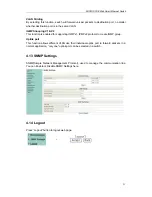
Page 32: ...enabled for supporting IGMPv1 IPMPv2 protocol to create IGMP group Uplink port This function allows different VLAN use their individual uplink port to forward packets In a normal application only one uplink port can be selected in a switch 4 13 SNMP Settings SNMP Simple Network Management Protocol used to manage the communication line You can Enable or Disable SNMP Settings here 4 14 Logout Press ...

Page 33: ...V 50 60HZ Power consumption Dimensions L W H 440 208 44 mm Environment Operating Temperature 0 40 Operating Humidity 10 90 non condensing Storage Temperature 10 70 Storage humidity 5 90 non condensing MAC Address Learning Automatically learning automatically Update 4K Standards IEEE802 3 10Base T IEEE802 3u 100Base TX IEEE802 3af IEEE802 3at Network Media RJ 45 10BASE T UTP category 5 cable maximu...

Reviews: