3
2.2. Rear
View
8-Port
Figure 3: 8-port IP-KVM rear view
16-Port
Figure 4: 16-port IP-KVM rear view
Ethernet LED Indicators:
IP-Ready:
ORANGE
LED
blinking per second when system is ready.
Ethernet-Link:
GREEN
LED
indicates that Ethernet connection established.
2.3. Single stage installation
2.3.1. Precaution:
Please turn off computers and devices when you start to install KVM Switch.
For computers with Keyboard Power On function, please unplug the power
cords in advance. Otherwise, the switch might not work properly.
If your computeres work under Windows 98, please connect KVM switch to
computers via PS/2 ports, because Windows 98 does not support installation
at first time as through USB HID installation driver.
Some kind of old computers must enable USB setting in BIOS in advance
to make USB interface work.
This KVM switch does not guarantee to fully support USB keyboard with
USB HUB.
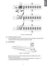
(Optional) Connect the USB connectors of USB A-mini cable to the host
computer and the IP-KVM module while for remote mass storage control.
Connect one end of Ethernet cable to ethernet jack of IP-KVM, and the
other end to the Remote Console computer.
English


