INSTALLATION MANUAL
DIGIWAY PLUS
23
cdvi.com
cdvigroup.com
EN
Part II: Electrical connections
Part II: Electrical connections
The range of motors for the double door is described in the following table:
The range of motors for the double door is described in the following table:
Double door total width
Leaves width
p/n Articulated Arm
p/N Sliding Arm
1600 mm
1600 mm
70 - 80 mm
70 - 80 mm
DWPD10216ACD
DWPD10216ACD
DWPD10216SCD
DWPD10216SCD
1700 mm
1700 mm
81 - 85 mm
81 - 85 mm
DWPD10217ACD
DWPD10217ACD
DWPD10217SCD
DWPD10217SCD
1800 mm
1800 mm
86 - 90 mm
86 - 90 mm
DWPD10218ACD
DWPD10218ACD
DWPD10218SCD
DWPD10218SCD
1900 mm
1900 mm
91 - 95 mm
91 - 95 mm
DWPD10219ACD
DWPD10219ACD
DWPD10219SCD
DWPD10219SCD
2000 mm
2000 mm
96 - 100 mm
96 - 100 mm
DWPD10220ACD
DWPD10220ACD
DWPD10220SCD
DWPD10220SCD
With the motors DWPD, with central profi le, the product comes already equipped with synchronization cable.
With the motors DWPD, with central profi le, the product comes already equipped with synchronization cable.
It is also possible to use 2 single door units ( DWP102x) to automate a double leaf door with synchronization of each leaf.
It is also possible to use 2 single door units ( DWP102x) to automate a double leaf door with synchronization of each leaf.
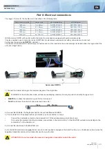
For that use the serial cable
For that use the serial cable
DWPCS
DWPCS
( optional ).
( optional ).
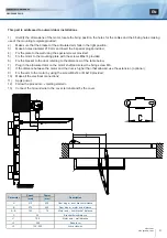
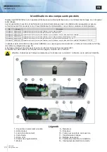
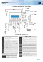
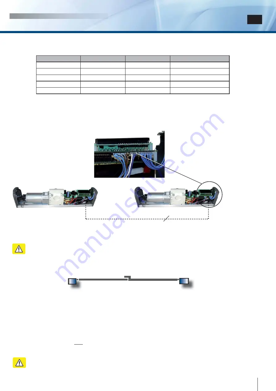
The cable is terminated with 2 special 3-way connectors and must be inserted in the corresponding slot located under the logic card of the
The cable is terminated with 2 special 3-way connectors and must be inserted in the corresponding slot located under the logic card of the
unit ( see image below ).
unit ( see image below ).
3
3
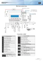
1 ) Connect the motors referring to the electrical diagram of the single door.
1 ) Connect the motors referring to the electrical diagram of the single door.
WARNING: in the double door mode, with leaves overlapping (rebated), it is very important to identify the type of unit
WARNING: in the double door mode, with leaves overlapping (rebated), it is very important to identify the type of unit
•
•
MASTER
MASTER
unit drives
unit drives
the leaf which opens fi rst and closes last
the leaf which opens fi rst and closes last
•
•
SLAVE
SLAVE
unit drives
unit drives
the leaf which opens last and closes fi rst
the leaf which opens last and closes fi rst
Serial cable DWPCS
Serial cable DWPCS
Master
Master
Slave
Slave
2 ) Connect the RADARs, the Day/Night switch to the unit identifi ed as MASTER
2 ) Connect the RADARs, the Day/Night switch to the unit identifi ed as MASTER
3 ) The contacts NC of the safety devices ( photocells ) can be connected in 2 ways:
3 ) The contacts NC of the safety devices ( photocells ) can be connected in 2 ways:
•
•
Connect the photocells contacts to the terminals 5,6,7 of the corresponding unit electronic card
Connect the photocells contacts to the terminals 5,6,7 of the corresponding unit electronic card
•
•
Put in serial the contacts of all the photocells, connect them to the terminals 5,6,7 of the MASTER unit and make a bridge to the
Put in serial the contacts of all the photocells, connect them to the terminals 5,6,7 of the MASTER unit and make a bridge to the
contacts 5,6,7 of the SLAVE unit.
contacts 5,6,7 of the SLAVE unit.
4 ) Connect the electrolock to the MASTER unit
4 ) Connect the electrolock to the MASTER unit
5 ) On the SLAVE unit memorize
5 ) On the SLAVE unit memorize
only
only
the 4ch remote control needed to navigate in the SLAVE unit menu, on the Master unit memorize the
the 4ch remote control needed to navigate in the SLAVE unit menu, on the Master unit memorize the
navigation transmitter and any other transmitter used to open the door
navigation transmitter and any other transmitter used to open the door
ATTENTION : Do not memorize the same 4ch navigation transmitter on both the units!
ATTENTION : Do not memorize the same 4ch navigation transmitter on both the units!

