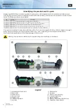
DIGIWAY PLUS
INSTALLATION MANUAL
EN
Sliding arm version
Sliding arm version
First of all, check the stability of the door which has to be motorized, verifying that regularity of the motion in both
First of all, check the stability of the door which has to be motorized, verifying that regularity of the motion in both
directions ( open and close ) is without any friction from the complete close to the complete open status. If this is
directions ( open and close ) is without any friction from the complete close to the complete open status. If this is
not the case, make necessary improvements to the structure. Remove any manually operated lock (eg. requiring a
not the case, make necessary improvements to the structure. Remove any manually operated lock (eg. requiring a
physical lowering of the handle to open the door).
physical lowering of the handle to open the door).
Digiway plus
Digiway plus does not need a door-stop fi tted
does not need a door-stop fi tted to complete the open cycle.
to complete the open cycle.
This type of installation is addressed to inswing doors.
This type of installation is addressed to inswing doors.
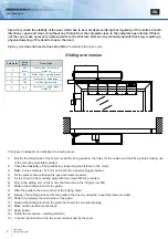
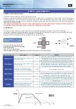
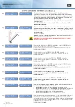
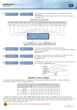
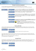
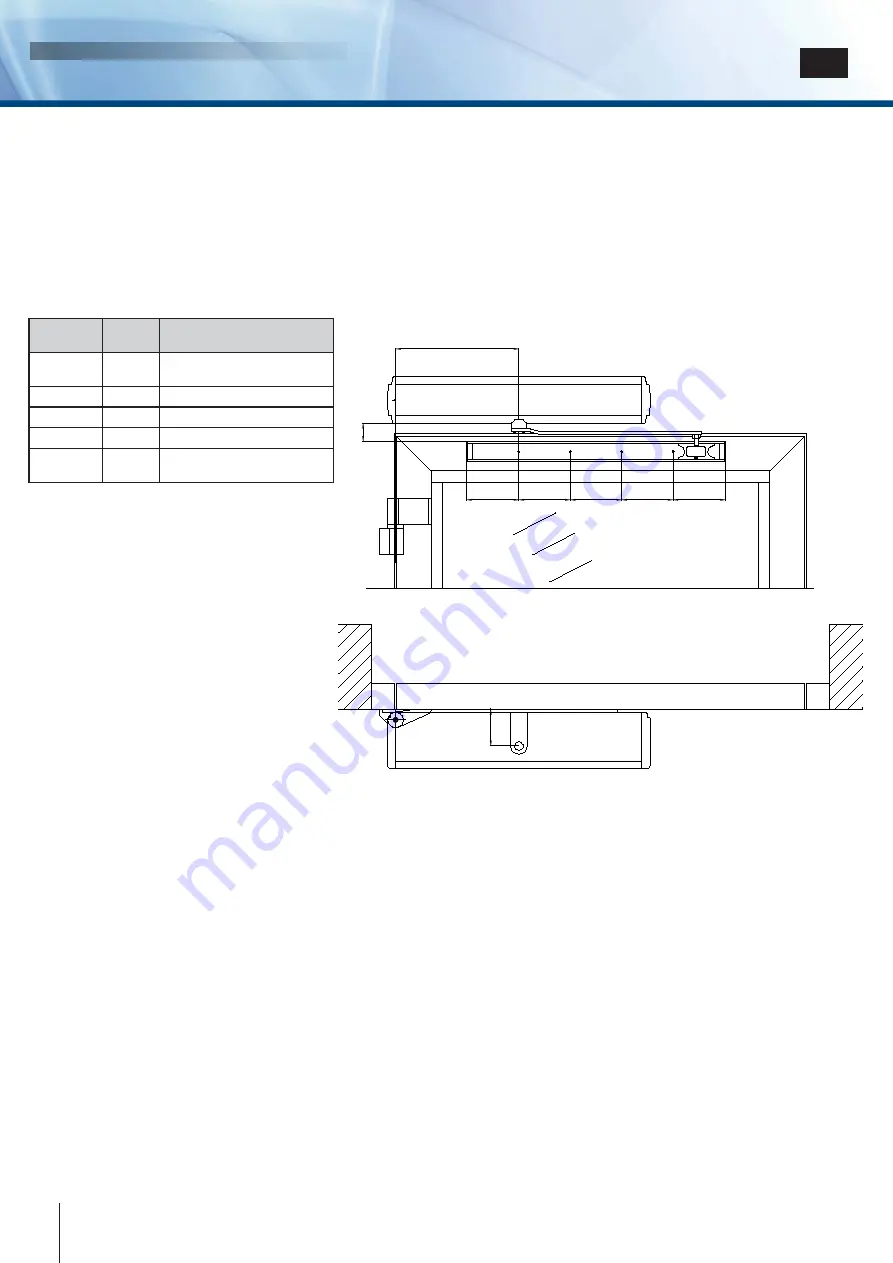
1) Identify the dimensions of the motor, locate the fi xing position, the holes for the cables and the 6 fi xing holes making use
1) Identify the dimensions of the motor, locate the fi xing position, the holes for the cables and the 6 fi xing holes making use
of the mounting template provided;
of the mounting template provided;
2) Check the feasibility of the guide fi xing, respecting the distance to the motor;
2) Check the feasibility of the guide fi xing, respecting the distance to the motor;
3) Make 6 holes diameter Ø 8 mm and insert the 6 special plugs provided ;
3) Make 6 holes diameter Ø 8 mm and insert the 6 special plugs provided ;
4) Fix the plate to the wall using the special screws provided;
4) Fix the plate to the wall using the special screws provided;
5)
Fix the motor to the mounting plate with the screws M6x14 provided;
5)
Fix the motor to the mounting plate with the screws M6x14 provided;
6) Plug-in the sliding arm on the motor shaft and screw the fi xing screw M6;
6) Plug-in the sliding arm on the motor shaft and screw the fi xing screw M6;
7) Slide-in the sliding block into the guide;
7) Slide-in the sliding block into the guide;
8) Offer the guide to the door and mark the 4 fi xing holes;
8) Offer the guide to the door and mark the 4 fi xing holes;
9) Remove the sliding block and fi x the guide to the door by using the 4 special screws provided;
9) Remove the sliding block and fi x the guide to the door by using the 4 special screws provided;
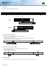
10) Slide-in completely the white strip on the guide;
10) Slide-in completely the white strip on the guide;
11) Slide-in the sliding block into the guide and insert the two lateral plugs;
11) Slide-in the sliding block into the guide and insert the two lateral plugs;
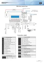
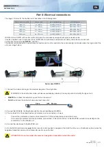
12) Make all the electrical connections;
12) Make all the electrical connections;
13) Apply power;
13) Apply power;
14) Follow the procedure : «Getting started»;
14) Follow the procedure : «Getting started»;
15) Connect the Ground wire to the cover terminal and fi x the cover.
15) Connect the Ground wire to the cover terminal and fi x the cover.
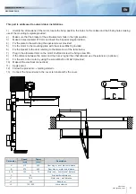
E
A
B
C
D
D
D
C
Parameter
Value
(mm)
Description
A
A
240
240
(max)
(max)
Door hinge – motor axis
Door hinge – motor axis
distance
distance
B
B
35
35
Motor cover – guide distance
Motor cover – guide distance
C
C
102
102
Motor axis - guide edge
Motor axis - guide edge
D
D
100
100
Guide holes interaxis
Guide holes interaxis
E
E
70,5
70,5
Motor axis - vertical plane
Motor axis - vertical plane
distance
distance
8
cdvi.com
cdvigroup.com


