background image

5

APERTURA 90°

APERTURA 110°

MONTAJE DE LOS OPERADORES

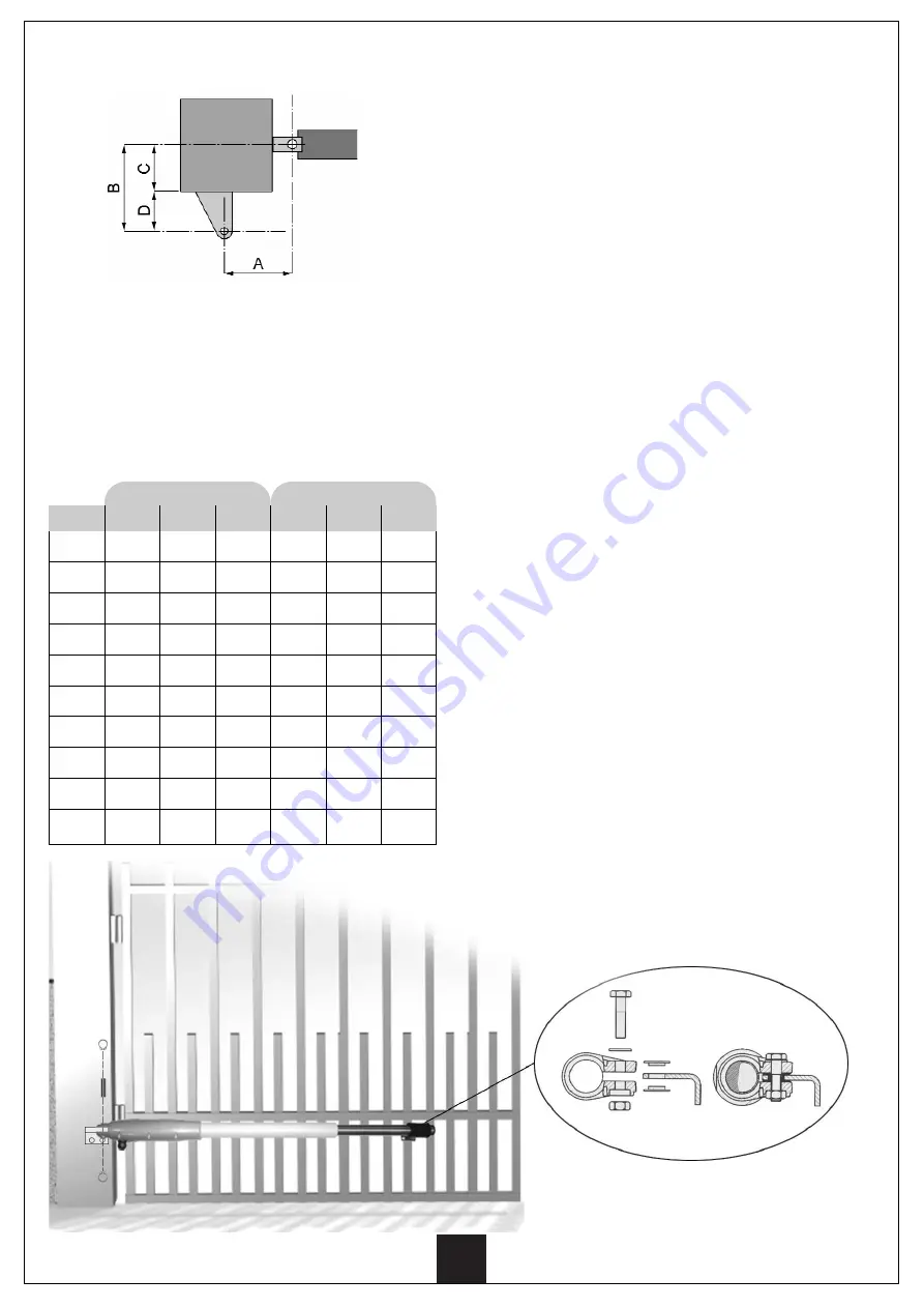
Para efectuar una correcta instalación de los 
operadores y garantizar un funcionamiento óptimo de la
automatización, es necesario respetar las cotas de
medición de la tabla de abajo.
Eventualmente, modificar la estructura de la puer ta, de
forma que se adapte a uno de los casos de la tabla de
abajo.

D(mm)

105

105

90

80

70

60

50

50

/

/

B(mm)

135

145

140

140

140

140

140

150

/

/

A(mm)

130

120

120

120

120

120

120

110

/

/

D(mm)

125

115

105

105

90

80

70

60

50

50

B(mm)

155

155

155

165

160

160

160

160

160

160

A(mm)

130

130

120

120

120

120

120

120

120

110

C(mm)

30

40

50

60

70

80

90

100

110

120

Para instalar de forma correcta los operadores a la
puer ta seguir atentamente los siguientes puntos:

Marcar en los postes las medidas A y B que se 
consideren más opor tunas.

Instalar los sopor tes 5 a los postes y posicionar los 
operadores en ellos.

Introducir el perno 6 en el agujero y bloquearlo en 
las dos extremidades utilizando los dos seeger 7.

DURANTE TODAS ESTAS OPERACIONES EVITAR  
MANTENER EL OPERADOR COLGADO; tiene que 
aguantarse horizontalmente sin que cuelgue por un solo
punto. 

Montar el sopor te 8 con la pinza tubular 9 como 
indicado en la figura.

Montar las dos arandelas de plástico 10 en el 
sopor te 8. Eventualmente utilizar grasa para sujetar
las, de modo que durante el montaje de la pinza 
tubular 9 no se desplacen o caigan.

Posicionar el soporte 8 con las arandelas de plástico
10 en la pinza tubular 9 alineando los agujeros.
CUIDADO! LA PINZA TUBULAR TIENE QUE SER 
MONTADA CON EL LADO DEL ALOJAMIENTO 
HEXAGONAL HACIA ABAJO.

Colocar la tuerca 11 en su sede (por debajo), 
introducir la arandela 12 en el tornillo 13, montar el 
tornillo 13 y atornillar sin hacer excesiva fuerza.

Sacar completamente el vástago del operador 1 
desatornillándolo manualmente; llegados al tope 
volver a atornillarlo de una vuelta.

Introducir el vástago del operador 1 en la pinza 
tubular 9 (tuerca en la par te de abajo) y posicionarla 
a 1,5 cm de la punta del vástago.

Cerrar la puer ta y bloquearla a su tope central, 
posicionar el operador horizontalmente, localizar la 
posición de los dos agujeros del sopor te 8 sobre la 
hoja e instalarla de forma que aguante grandes 
esfuerzos.

Aflojar el tornillo 13 de la pinza tubular 9. La 
misma, desplazándose por toda la longitud del 
vástago del operador, permite verificar que la 
aper tura de la hoja sea total. Esta comprobación a 
de hacerse solo para simular una aper tura manual 
de emergencia por falta de luz (en el caso de no 
utilizar batería de emergencia) o de no-funcionamiento
del automatismo. Volver a cerrar, bloqueando la 
puer ta y, apretar el tornillo 13 de la pinza tubular 9.

Summary of Contents for KIT BATT12V

Page 1: ...TE COM FOLHAS AT 2 m DE COMPRIMENTO 12V KIT FOR SWING GATES UP TO 2 m LEAF KIT POUR PORTAILS VANTAIL JUSQU 2 m DE LONGUEUR BAUSATZ F R GITTERT RE DIE T RFL GEL MIT EINER MAXIMALER L NGE VON 2 m HABEN...

Page 2: ...KIT BATT12V INSTRUCCIONES 1 INSTRU ES 11 INSTRUCTIONS 21 NOTICES 31 ANLEITUNGEN 41 E P GB F D...

Page 3: ...ES PRELIMINARES 4 MONTAJE DE LOS OPERADORES 5 ESQUEMA DE INSTALACI N 6 DESCRIPCION DEL CUADRO DE MANIOBRAS 7 CONEXION DE LOS BORNES 7 CARACTERISTICAS TECNICAS 7 INSTALACION DE LA BATERIA 8 PROGRAMACIO...

Page 4: ...omatismos LA AUTOMATIZACION DEBE SER REALIZADA EN CONFORMIDAD A LAS VIGENTES NORMATIVAS EUROPEAS EN 60204 1 Seguridad de la maquinaria Equipamiento electrico de las maquinas partes 1 reglas generales...

Page 5: ...a de se alizaci n EGG12 1 5 Soporte para instalaci n operadores al poste 2 6 Perno para instalaci n operador 2 7 Seeger para sujetar perno 4 8 Soporte para instalaci n operadores a la hoja 2 9 Pinza t...

Page 6: ...siguientes puntos bisagras y pernios en estado ptimo y oportunamente lubricados ning n obst culo debe impedir el movimiento ning n roce entre el suelo y las hojas dilataci n mec nica de 7 a 8 mm m n s...

Page 7: ...ico 10 en el soporte 8 Eventualmente utilizar grasa para sujetar las de modo que durante el montaje de la pinza tubular 9 no se desplacen o caigan Posicionar el soporte 8 con las arandelas de pl stico...

Page 8: ...de la puerta para evitar utilizar cables de conexi n excesivamente largos Utilizar tacos adecuados al tipo de pared ej ladrillo o cemento INSTALACION DE LA LAMPARA Y DE LOS DISPOSITIVOS DE COMANDO pul...

Page 9: ...s Eliminaci n del riesgo de electrificaci n accidental de las masas met licas conectadas al cuadro operadores hojas y accesorios Seguridad antiaplastamiento realizada mediante detecci n de esfuerzo en...

Page 10: ...a RX durante 10 segundos El led L1 emite 5 destellos individuales para indicar que ha cancelado todo el contenido de la memoria Una vez memorizados las funciones asociadas a las teclas del emisor qued...

Page 11: ...ando se presentan las siguientes condiciones el movimiento de las hojas se detiene durante un tiempo definido como tiempo de pausa DURANTE LA APERTURA Si interviene el sensor antiaplastamiento el movi...

Page 12: ...ransmisi n cierre del contacto el sistema est en STOP ya que el cuadro ve en los bornes indica dos como STOP un contacto abierto Si el pulsador de STOP siendo opcional no est insta lado puede suceder...

Page 13: ...M12V 14 OPERA ES PRELIMINARES 14 MEDIDAS DE INSTALA O 15 ESQUEMA DA INSTALA O 16 DESCRI O DA CENTRALE DE COMANDO 17 ESPECIFICA ES T CNICAS 17 LIGA ES AO BORNE 17 INSTALA O ACUMULADOR 18 PROGRAMA O 18...

Page 14: ...m quinas 98 37 EEC apenso IIA obrigat rio respeitar as seguintes normas para cerramentos veiculares automatizados EN 12453 EN 12445 EN 12978 e as eventuais prescri es nacionais A instala o a montante...

Page 15: ...4 Luz intermitente EGG12 1 5 Estribo para fixa o do actuador na folha 2 6 Pino par a fixa o do actuador 2 7 Seeger para fixa o do pino 4 8 Estribo para fixa o do actuador na folha 2 9 Pin a tubular 2...

Page 16: ...intes pontos gonzos e eixos se devem estar em perfeito estado e oportunamente lubrificados nenhum obst culo deve impedir o movimento nenhum atrito com o solo e entre as portas dilata o mec nica de 7 a...

Page 17: ...elas de pl stico 10 no suporte 8 Eventualmente utilizar gordura para sujeit las de modo que durante a montagem da pin a tubular 9 n o se desloquem ou caiam Posicionar o suporte 8 com as arruelas de pl...

Page 18: ...nstala o ESQUEMA DA INSTALA O INSTALA O DA CAIXA EL CTRICA importante instalar a caixa el ctrica muito pr xima ao port o para evitar o uso de cabos de liga o excessivamente compridos Utilizar interval...

Page 19: ...istemas de auto ma o com tens o muito baixa que utilizam a PRG12 encontram se listadas abaixo Elimina o do risco de electrifica o acidental das massas met licas ligadas central actuadores portas e ace...

Page 20: ...der da seguinte forma Carregar e manter carregado na tecla RX durante 10 segundos O led L1 emite 5 piscadas singulares para indicar que cancelou todo o conte do da mem ria Uma vez memorizadas as fun e...

Page 21: ...s aparentes ent o seleccione como baixa Dip2 Tempo em fase de pausa Ao se apresentarem as seguintes condi es o movi mento das portas p ra durante um tempo definido como tempo de pausa DURANTE A ABERTU...

Page 22: ...icados como STOP um contacto aberto Se o bot o de STOP por ser opcional n o foi instala do poss vel que o fio de ponte sobre os bornes mar cados STOP seja inst vel neste caso deve se controlar e event...

Page 23: ...LIMINARY OPERATIONS 24 OPERATOR INSTALLATION 25 INSTALLATION LAYOUT 26 DESCRIPTION OF THE CONTROL UNIT 27 TERMINAL CONNECTIONS 27 SPECIFICATIONS 27 ACCUMULATOR INSTALLATION 28 PROGRAMMING 28 TIME AUTO...

Page 24: ...ion Machine Directive 98 37 EEC Annex IIA The automated vehicular gates shall comply with the following rules EN 12453 EN 12445 EN 12978 as well as any local rule in force Also the automation upstream...

Page 25: ...ansmitters TRC 4 DM 2 4 Flasher EGG12 1 5 Fastening bracket actuator to pillar 2 6 Fastening pin actuator 2 7 Fastening Seeger pin 4 8 Fastening bracket actuator to shutter 2 9 Clamp cylinder 2 10 Pla...

Page 26: ...as follows Pintles and pivots shall be in good order and properly lubricated Nothing shall block the movement No friction with earth and between the doors shall exist mechanical expansion from 7 to 8...

Page 27: ...nging from one single point Mount bracket 8 onto the clamp cylinder 9 as shown in figure Mount the two plastic washers 10 onto bracket 8 use some grease in order to secure them in place and prevent an...

Page 28: ...e gate to avoid too much long connecting wiring Make use of dowels which are suitable to the kind of wall for instance brick or cement INSTALLATION OF BLINKING LAMP AND CONTROL DEVICES safety and cont...

Page 29: ...of 12V D C actuators Benefits resulting from the very low voltage automations using PRG12PP are as follows No risk of accidental electrification of the metallic masses which are connected to the power...

Page 30: ...rd and keep it pressed for 10 seconds at least LED L1 will start blinking and at the same time the two motors one at a time will work by carrying out two opening and closing cycles respecti vely BE EX...

Page 31: ...hout any clear reason then set it on low sensitivity Dip 2 Pause time When the following situations occur the door movement stops for a period called pause time DURING THE OPENING If the anti squashin...

Page 32: ...to the STOP terminals Since the STOP button is optional if it has not been installed it could be the case that the jumper on the STOP terminals is instable then it will be necessary to check it and r...

Page 33: ...NAIRES 34 MONTAGE DES ACTIONNEURS 35 SCH MA D INSTALLATION 36 DESCRIPTION DE LA CENTRALE DE COMMANDE 37 BRANCHEMENTS AU BORNIERE 37 CARACT RISTIQUES TECHNIQUES 37 INSTALLATION ACCUMULATEUR 38 PROGRAMM...

Page 34: ...en mesure de d livrer l attestation de conformit pour l installation Directive 98 37 EEC IIA Il est obligatoire se conformer aux normes suivantes pour fermetures v hiculaires automatis es EN 12453 EN...

Page 35: ...4 DM 2 4 Clignotant EGG12 1 5 Patte de fixation op rateur sur pilier 2 6 Goujon de fixation op rateur 2 7 Seeger pour fixation du goujon 4 8 Patte de fixation op rateur sur vantail 2 9 Pince tubulair...

Page 36: ...oints suivants gonds et tourillons en tr s bon tat et graiss s de mani re opportune aucune entrave ne doit emp cher le mouvement aucun frottement contre le sol et entre les volets dilatation m canique...

Page 37: ...te 8 sur la pince tubulaire 9 selon la figure Monter les deux rondelles plastiques 10 sur la patte 8 utilisant du gras pour les fixer dans son logement et viter un d placement et chute pendant le mont...

Page 38: ...le voisinage imm diat du portail pour viter d avoir utiliser des c blages de raccordement excessivement longs Utiliser des chevilles adapt es au type de mur ex bri que ou b ton INSTALLATION DU CLIGNOT...

Page 39: ...ci dessous sont nonc s les avantages se rattachant l emploi de syst mes d auto matisation tr s basse tension qui utilisent la PRG12 limination du risque d lectrification accidentelle des masses m tal...

Page 40: ...ter en m me temps les moteurs un la fois entrent en mouvement et effec tuent 2 cycles d ouverture et 2 cycles de fermeture PR TER LE MAXIMUM D ATTENTION PENDANT L APPRENTISSAGE DES DELAIS ET EVITER D...

Page 41: ...volets s arr te pendant un temps d fini comme d lai de pause lorsque se manifestent les conditions suivantes PENDANT L OUVERTURE S il y a d clenchement du capteur contre les crasements ou d clencheme...

Page 42: ...ntrale voit aux bornes indiqu es STOP un contact ouvert Si le poussoir de STOP qui constitue une option n est pas install il se peut que le raccordement par pontage sur les bornes marqu es STOP soit i...

Page 43: ...VORBEREITNDE ARBEITSSCHRITTE 44 MONTAGE DER OPERATOREN 45 INSTALLATIONSPLAN 46 BESCHREIBUNG DER STEUERZENTRALE 47 ANSCHL SSE AM KLEMMENBRETT 47 TECHNISCHE DATEN 47 INSTALLATION DES AKKUMULATORS 48 PR...

Page 44: ...nur von geschulten Technikern vorgenommen werden DIE AUTOMATISIERUNG MUSS IN BEREINSTIMMUNG MIT DEN GELTENDEN EUROP ISCHEN NORMEN ERFOLGEN EN 60204 1 Sicherheit der Maschine elektrische Ausr stungen v...

Page 45: ...r die Befestigung der Stellglieder 2 am Pfeiler 6 Befestigungsstift Stellglied 2 7 Seegerring f r Stiftbefestigung 4 8 B gel f r die Befestigung des Stellgliedes am 2 Torfl gel 9 Befestigungsschelle 2...

Page 46: ...n zu pr fen Angeln und Stifte m ssen sich in einwandfreiem Zustand befinden und hinreichend geschmiert sein kein Hindernis darf die Bewegung beeintr chtigen es darf keine Reibung zwischen den Torfl ge...

Page 47: ...en Sie Schmierfett um die Scheiben in ihrem Sitz zu verankern und so ein Verrutschen oder L sen w hrend der Montage der Befestigungsschelle 9 zu vermeiden Positionieren Sie B gel 8 mit den montierten...

Page 48: ...r die Anschl sse zu lange Kabel erforderlich werden Verwenden Sie D bel die f r die jeweilige Art von Wand geeignet sind z B Ziegel oder Zement INSTALLATION DER BLINKLEUCHTE UND DER STEUERELMENTE Befe...

Page 49: ...it 12 Volt Gleichstrom Einbau Empf nger 433 MHz Superheterodynempfang Auf dem System k nnen bis zu 48 Sender der Serie Personal Pass Versorgung 230 VAC 50 Hz Max Motorbelastung 60 W Max Belastung des...

Page 50: ...blinken gleichzeitig setzen sich die Motoren in Bewegung und f hren zwei ffnungs und Schlie zyklen durch GEHEN SIE BEI DER EIGENERFASSUNG DER ZEITEN MIT GROSSER AUFMERKSAMKEIT VOR STELLEN SIE SICHER D...

Page 51: ...ig umgestellt werden Dip 2 STILLSTANDSZEITEN Unter den folgenden Bedingungen stoppt die Bewegung der Fl gel f r eine Dauer die als Pausenzeit definiert ist W HREND DES FFNENS Bei Ausl sen des Sensors...

Page 52: ...bezeichneten Klemmen einen offenen Kontakt erfasst Ist die Taste STOP da optional nicht installiert k nnte die Polbr cke an den mit BL bezeichneten Klemmen instabil sein Pr fen Sie in diesem Fall die...

Page 53: ......

Page 54: ......

Reviews: