E
N
G
L
IS
H
19
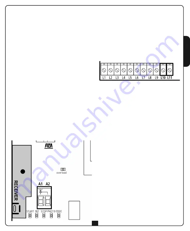
PLUG-IN RECEIVER
The control unit is suitable for plugging-in an MR1
series receiver with high sensitivity super-heterodyne
architecture.
m
PLEASE NOTE:
Disconnect the power to the
control unit before performing the following
operations. Pay the utmost attention to the
direction of insertion of plug-in modules.
The MR1 receiver module has 4 channels, each with
an associated command on the
CITY11
control unit:
• CHANNEL 1
START
• CHANNEL 2
PEDESTRIAN START
• CHANNEL 3
STOP
• CHANNEL 4
COURTESY LIGHTS
m
PLEASE NOTE:
Read the instructions supplied with the MR1
receiver thoroughly for details on programming the
4 channels and the operational logic.
EXTERNAL ANTENNA
It is recommended the external antenna be used in
order to guarantee maximum radio capacity.
Connect the antenna hot pole to terminal
A1
of the
control unit and the braiding to terminal
A2
.
ELECTRIC LOCK
A 12V electric lock can be mounted on the gate to
ensure a good closure of the shutters.
The electric lock is activated for a fixed time of
1.5 seconds.
The lock advance time is adjustable from 0.2 to
0.5 seconds (dip-switch 1)
Connect the cables of the electric lock between
terminals
L10
and
L11
of the control unit.
Summary of Contents for MOOV-B300 120V
Page 1: ......
Page 2: ......
Page 4: ......
Page 35: ......
Page 36: ......
Page 38: ......
Page 46: ...ITALIANO 8 TABELLA COLLEGAMENTI ELETTRICI...
Page 58: ...ENGLISH 20 ELECTRICAL CONNECTION TABLE...
Page 70: ...FRAN AIS 32 TABLEAU BRANCHEMENTS LECTRIQUES...
Page 82: ...ESPA OL 44 CUADRO DE CONEXIONES EL CTRICAS...
Page 94: ...PORTUGU S 56 TABELA CONEX ES EL CTRICAS...
Page 106: ...DEUTSCH 68 TABELLE ELEKTRISCHE ANSCHL SSE...
Page 118: ...NEDERLANDS 80 ELEKTRISCHE AANSLUITINGEN...
Page 123: ......
Page 124: ......
Page 126: ...L1 P1...
Page 148: ......
Page 150: ...Fig 1 Fig 2 Fig 3...
Page 151: ...Fig 4 SYNCHRO...
Page 152: ...Fig 5 NO SYNCHRO...


