background image


7

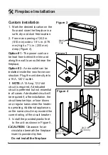
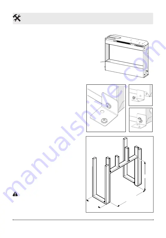
Figure 2

Media 

Tray

Custom Installation

1.  Mark the desired location on the 

floor and store the fireplace in a 

safe, dry and dust free location.

2.  Frame an opening of 24.0 in. 

(610 mm) wide x 18 

¾

 in. (476 

mm) high x 7 

 in. (200 mm) 

deep (Figure 4).

Option #1 

- The power cord can 

be lead from behind the trim and 

along the wall to an outlet near the 

fireplace.

Option #2

 - A new outlet can be 

installed inside the new frame con-

struction. Plug the unit directly into 

a 15 A, 120 V outlet.

!


NOTE:

 A 15 Amp, 120 Volt 

circuit is required. A dedicated 

circuit is preferred but not essential 

in all cases. A dedicated circuit will 

be required if, after installation, the 

circuit breaker trips or fuse blows 

on a regular basis when the heater 

is operating. Additional appliances 

on the same circuit may exceed the 

current rating of the circuit breaker.
3.  Install the provided plastic feet 

to the unit as shown in Figure 5.

 CAUTION: 

Clearance for air 

circulation beneath the fireplace 

insert is provided by feet. 

Do not install the fireplace 

 Fireplace Installation


Figure 3

Figure 4

24.0 in. 

(610 mm)

18 ¾ in.


(476 mm)

7 ⅞ in. 

(200 mm)

Summary of Contents for 6908922359

Page 1: ...TION Always read this manual first before attempting to install or use this fireplace For your safety always comply with all warnings and safety instructions contained in this manual to prevent person...

Page 2: ...emphasize CAUTION Procedures and techniques which if not carefully followed will result in damage to the equipment WARNING Procedures and techniques which if not carefully followed will expose the us...

Page 3: ...www dimplex com customer_support For Troubleshooting and Technical Support OR Toll Free 1 888 DIMPLEX 1 888 346 7539 Monday to Friday 8 00 a m to 4 30 p m EST In order to better serve you please have...

Page 4: ...er contact Dimplex Technical Service at 1 888 346 7539 Do not use outdoors IMPORTANT INSTRUCTIONS Never locate this heater where it may fall into a bathtub or other water container Do not run cord und...

Page 5: ...roperly grounded fused and polarized outlets Disconnect all power supply before performing any cleaning maintenance or relocation of the heater When transporting or storing the heater and cord keep in...

Page 6: ...sk of fire do not store or use gaso line or other flammable vapors or liquids in the vicinity of the heater Front Glass Installation 1 Unpack the glass assembly 2 If applicable carefully pour and even...

Page 7: ...into a 15 A 120 V outlet NOTE A 15 Amp 120 Volt circuit is required A dedicated circuit is preferred but not essential in all cases A dedicated circuit will be required if after installation the circu...

Page 8: ...TRIP MEDIA BED LED ASSEMBLY 120V 12V AC DC CUTOUT FLICKER MOTOR BLOWER MOTOR DISPLAY CONTROL BOARD M T M ELEMENT AC DC ADAPTER SWITCHBOARD RELAY BOARD THERMISTOR LOGSET LED ASSEMBLY LED LIGHT ASSEMBLY...

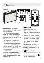
Page 9: ...ting any operation with the remote pull the plastic insulator strip out from between the remote casing and battery cover A Standby Turns the unit On and Off Activated by pressing the Standby button on...

Page 10: ...odor when first used This odor is a normal condi tion caused by initial heating of internal heater D E Thermostat Controls Adjusts the temperature set point to your individual requirements Once the de...

Page 11: ...g the button repeat edly until the sleep timer displays nothing Operation and enable the heater NOTE When the heater has been disabled and either the or the is pressed the On Screen Display will indic...

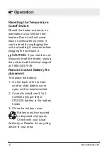
Page 12: ...ed to con tinuously reset the heater unplug the unit and call technical support at 1 888 346 7539 Remote Control Battery Re placement To replace the battery 1 On the back of the remote control slide b...

Page 13: ...be cleaned with a damp cloth The front glass panel should be completely dried with a lint free cloth to prevent water spots To prevent scratching do not use abrasive cleaners or spray liquids on the g...

Page 14: ...en tested and inspected prior to shipment and subject to the provisions of this warranty Dimplex warrants such products to be free from defects in material and workmanship for a period of 12 months fr...

Page 15: ...transportation costs Such costs shall be the purchaser s responsibility What Dimplex and its dealers and service agents are also not responsible for IN NO EVENT WILL DIMPLEX OR ITS DIRECTORS OFFICERS...

Page 16: ...5902580200RP Front Glass 5902640100RP Felt Feet Pads set of 4 8600140101RP Plastic Foot Set 8800090101RP Log Set Assembly 0440590500RP Acrylic Media 1400150100RP Display Control Board Logset version 3...

Reviews: