background image

Service Manual

Model 

Part Number

DFI400L 6909050241

DFI400R 6909050242

DFI600L 6909050261

7400770000R00

In keeping with our policy of continuous product development, we reserve the right to make changes without notice.
© 2013 Dimplex North America Limited

Dimplex North America Limited

1367 Industrial Road   Cambridge ON Canada N1R 7G8
1-888-346-7539   www.dimplex.com

REV PCN

DATE

00

-

1-NOV-13

IMPORTANT SAFETY INFORMATION

: Always read this manual first before attempting to service this cassette. For your 

safety, always comply with all warnings and safety instructions contained in this manual to prevent personal injury or prop-

erty damage.

Summary of Contents for 6909050241

Page 1: ...2013 Dimplex North America Limited Dimplex North America Limited 1367 Industrial Road Cambridge ON Canada N1R 7G8 1 888 346 7539 www dimplex com REV PCN DATE 00 1 NOV 13 IMPORTANT SAFETY INFORMATION...

Page 2: ...equipment WARNING Procedures and techniques which if not carefully followed will expose the user to the risk of fire serious injury or death Operation 3 Maintenance 4 Exploded Parts Diagram 5 Replacem...

Page 3: ...lways ensure that the appliance is in a level position The manual controls for the cassette are located on the top of the unit below the control cover Figure 1 A On Off Switch Supplies power to the ca...

Page 4: ...ng of skin Light bulb requirement 45W 12VAC halogen bulbs type MR 16 Contact Dimplex Technical Service at 1 888 346 7539 for replacement bulbs 1 Leaving the flame effect on remove the media if appli c...

Page 5: ...00RP 8 Cap for Refill Container 0441440300RP 9 Top Cover Assembly 9600670100RP 10 Water Tank 0441380100RP 11 Fan Assembly 5300300100RP 12 Fan Housing Assembly 9600540100RP 13 Fan Filter 8600300100RP 1...

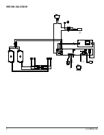
Page 6: ...6 www dimplex com WIRING DIAGRAM TRANSDUCER MALE JACK DC FAN MOTOR WHITE MAINS 3 CORE CABLE BLACK WHITE...

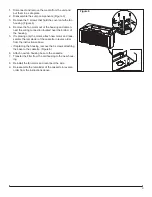
Page 7: ...nnector and the remote control receiver to release the wires 5 Re assemble the remainder of the cassette in reverse order from the instructions above TRANSFORMER REPLACEMENT Tools Required Philips hea...

Page 8: ...forming any maintenance 1 Disconnect and remove the media from the unit and put them in a safe place 2 Remove the 4 screws that secure the front grill to the cassette housing Figure 4 3 Locate the cor...

Page 9: ...he bottom of the housing 5 If replacing only the motor attach new motor and reas semble the remainder of the cassette in revers order from the instructions above If replacing the housing remove the 3...

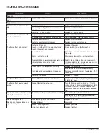
Page 10: ...ent mist Add 1 8 tsp of table salt to water reservoir to introduce electrolytes only repeat when mist is not being produced correctly Check that the fan is operating correctly Replace fan assembly Ens...

Reviews: