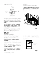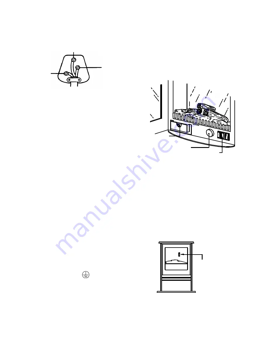
Preperation for Use
Neon's for indicating
operation level
Fig. 1
This heater must be used on an AC ~ supply only and the
voltage marked on the heater must correspond to the supply
voltage.
For your convenience, the heater is fitted with a rewirable
plug incorporating a 13 amp fuse. In the event of replacing
the fuse supplied, a 13 amp fuse approved by ASTA to BS
1362 must be used.
IMPORTANT: if the plug is not suitable for your socket, the
13 amp plug should be removed and the appropriate plug
fitted in accordance with the wiring instructions below.
Note:
When either the remote control or the manual controls
are used, the neon’s will come on for 3 seconds indicating
the relevant setting.
(see fig.2)
BLUE - NEUTRAL
BROWN - LIVE
Fig. 2
GREEN AND YELLOW - EARTH
As the colours of the wires in the mains lead may not
correspond with the coloured markings identifying the
terminals in your plug, proceed as follows:
Connect the BROWN wire to the terminal marked L or
coloured
RED
.
Connect the BLUE wire to the terminal marked N or coloured
BLACK
.
Connect the GREEN AND YELLOW wire to the terminal
marked E or by the earth symbol Or coloured
GREEN
or
GREEN AND YELLOW.
If a 3-pin 15 amp plug is used this should be protected by a
15 amp fuse either in the plug or adapter, or the distribution
board.
If in doubt consult your
electrician
.
Operation
The controls are located behind the door see Fig1.
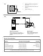
To operate the stove either manually or by using the remote
control, the standby switch must first be turned on. (see Fig.
4).
The red indicator mark on the switch will be visible when it is
turned on.
E. Earth
Green - Yellow
L. Live
Brown
N. Neutral
Blue
Wiring
a 15 amp plug
WARNING: THIS APPLIANCE MUST BE EARTHED
Remote Control
located in pocket
for details on
controls see
Fig. 4
Thermostat Knob

