background image

INSTALLATION

NOTE:

 To prevent personal injury always use a licensed electrician to install new outlets or

circuits.

1.  Select a suitable location that is not susceptible to moisture and is away from drapes,

furniture and high traffic.

2. For ease of electrical connections you may wish to locate the fireplace near an exist-

ing power supply outlet.  Ensure that the socket outlet will be accessible after installa-
tion of the fireplace.

3. Plan your electric power supply.  A 10 amp, 240 volt circuit is required.  A dedicated

circuit is preferred but not essential in all cases.  A dedicated circuit will be required if
after installation, the circuit breaker or fuse trips.  Additional appliances may exceed
the current rating of the circuit breaker or fuse.

4.  Assemble a surround mantle and place it in the desired location.

5. Remove the fireplace unit from the package.

6. Set the unit in front of the mantle opening. Plug the power supply cord into the socket

outlet.

7. Push the fireplace into the surround mantle unitil the trim is flush with the mantle

surface, and centered within the opening.

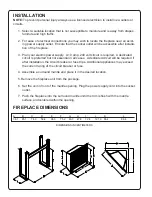
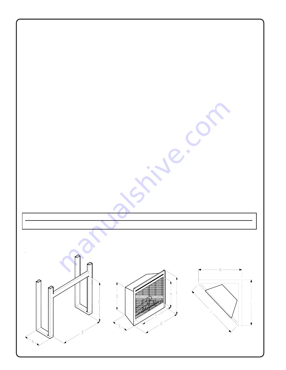
FIREPLACE DIMENSIONS

A

B

C

D

E

F

G

H

I

J

K

L

38.1

85.1

74.9

58.4

36.3

75.2

83.3

47.8

72.4

121.9

86.4

86.4

DIMENSIONS IN CENTIMETERS


Summary of Contents for BF 30' series

Page 1: ...INSTALLATION USERS GUIDE FOR THE ELECTRIC INSERT FIREPLACE BF 30 series 7205131100rev01...

Page 2: ...of this manual 2 The heater on your fireplace may emit a slight harmless odor when first used This odor is a normal condition caused by the initial heating of internal heater parts and will not occur...

Page 3: ...applinace in front of a fixed socket outlet 16 To disconnect the fireplace turn the controls off then remove the plug from the socket outlet 17 Do not insert or allow foreign objects to enter any ven...

Page 4: ...edicated circuit is preferred but not essential in all cases A dedicated circuit will be required if after installation the circuit breaker or fuse trips Additional appliances may exceed the current r...

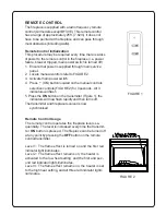
Page 5: ...lection controls FIGURE 2 for 3 seconds All 3 indicators will flash 5 Press the ON button on the transmitter Figure 1 the indicators will now flash rapidly and then turns off The transmitter and firep...

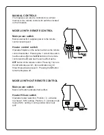
Page 6: ...he side of this switch has the same effect as the ON button on the remote control and the O side has the same effect as the OFF button of the remote control Pressing once to the left activates Level 1...

Page 7: ...in tenance or cleaning Bulb Requirements Quantity 4 clear chandelier or candelabra lamps with an E 14 socket base 60 watt rating CAUTION DO NOT EXCEED 60 WATTS PER LAMP TO REPLACE LAMPS 1 Open the ste...

Page 8: ...loss or damage arising out of the use of or inability to use the product The warranty will not apply if in the sole judgment of the Company damage or failure has resulted from accident alteration misu...

Reviews: