background image

12 


www.dimplex.com

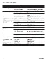
PROBLEM

CAUSE

SOLUTION

general

Circuit breaker trips or fuse 

blows when unit is turned on

Short in unit wiring.

Trace wiring in unit.

Improper circuit current rating

Additional appliances may exceed the current rating 

of the circuit breaker or fuse.  Plug unit into another 

outlet or install unit on a dedicated 15 amp circuit.

Unit turns on or off by itself

Remote control has a similar frequency 

to other remotes in the area.

Replace Remote Control.  Initialize to Remote Control 

Receiver.

Radio frequency disturbance from out-

side sources.

Replace Remote Control and Remote Control Re-

ceiver where necessary.  Initialize Remote Control and 

Receiver

Defective Remote Control Receiver

Replace Remote Control Receiver.  Initialize to Re-

mote Control.

Lights dim in room while the unit 

is on

Unit is drawing close to circuit current 

rating

Move the unit to another outlet or install unit on a dedi-

cated 15 amp circuit

Appearance

Fireplace does not turn on in 

Manual Mode

Improper operation

Refer to Operation Section

No incoming power from the electrical 

wall socket

Check Fuse/Breaker Panel

Defective On/Off Switch

Replace On/Off Switch

Defective Remote Control Receiver

Replace Remote Control Receiver. Initialize with Re-

mote Control.

Fireplace does not turn on in 

Remote Mode

Improper operation

Refer to Operation Section

Remote control not initialized to fireplace

Initialize the remote control

Loose wiring

Check wiring connections

Remote Control not working

Install new battery into the Remote Control.  Reinitial-

ize remote control where necessary
Replace Remote Control Receiver where necessary.  

Initialize Remote Control Receiver to Remote Control.

Defective Remote Control Receiver

Replace Remote Control Receiver.  Initialize to Re-

mote Control

Flame Frozen

Loose wiring

Check wiring connections

Defective flicker motor

Replace flicker motor

Flame not bright or flame not 

visible

Burnt out light bulbs

Replace light bulbs/

Loose wiring

Check wiring connections

Defective light harness

Replace light harness

Log set dim, not glowing

Burnt out light bulbs

Replace light bulbs

Flame Shudder

Defective flicker motor

Replace flicker motor

Light leaking around the log set

Log set not positioned properly

Check log set for proper fit

TROUBLESHOOTINg gUIDE

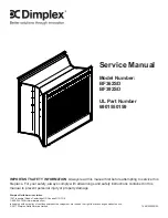
Summary of Contents for BF362SD

Page 1: ...ice 2011 Dimplex North America Limited Dimplex North America Limited 1367 Industrial Road Cambridge ON Canada N1R 7G8 1 888 346 7539 www dimplex com IMPORTANT SAFETY INFORMATION Always read this manual first before attempting to service this fireplace For your safety always comply with all warnings and safety instructions contained in this manual to prevent personal injury or property damage ...

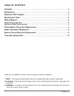
Page 2: ... in damage to the equipment Warning Procedures and techniques which if not carefully followed will expose the user to the risk of fire serious injury or death Operation 3 Maintenance 4 Exploded Parts Diagram 5 Replacement Parts 5 Wiring Diagram 6 Switch Replacements 8 On Off 3 Position Heater Switches 8 Flicker Motor Flicker Rod Replacement 8 Heater Assembly Replacement 9 Remote Control Receiver R...

Page 3: ...e remote control receiving unit When placed in the On position Level 1 indicator will flash 3 Position Heater Switch Pressing activates Level 1 once the flame effect is turned on and the first red indicator light is activated Level 2 twice the flame effect remains on the heater is activated to the low heat setting and the first and second red indicator lights are activated Level 3 three times the ...

Page 4: ...he plastic 5 grommet which holds the end of the rod in the left bracket Grasp and turn it turn releasing it from the slot in the bracket and then lift it out of the bracket The motor side of the rod may be attached to the motor 6 in one of two ways Secured with a spring attach needle nose pliers to the spring on the motor shaft and pull while rotating in the same direction of the spring winding Se...

Page 5: ...800070700RP REMOTE CONTROL 7 MOD 0 A 3000200200RP MOD B C 3000370600RP 6 2 3 4 5 9 10 8 7 13 12 11 1 Replacement Parts REMOTE CONTROL RECEIVER 8 MOD 0 A 3000200700RP MOD B 3000430800RP MOD C 3000820500RP PARTIALLY REFLECTIVE GLASS 9 5900160600RP GLASS SUPPORT STRIP 10 0438290100RP MESH CURTAIN 11 8800240103RP CURTAIN ROD 12 8800250100RP LIGHT SOCKETS WITH HARNESS 13 2500090100RP 4 12 11 1 9 ...

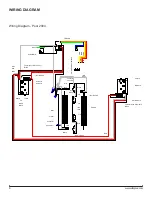
Page 6: ...ack Green Orange Red Yellow Thermal Cut Off Jumper 1 Black Thermal Cut Off Jumper 2 Black Connector Connector Connector Connector Connector Connector Bulb Bulb Bulb Bulb PC Board Power Switch On Off Momentary Switch Flicker 1 Flicker 2 Motor Blower 1 Motor Blower 2 Motor Flicker 1 Motor Flicker 2 Blower 1 Blower 2 Heater 1 Heater 2 N Wiring Diagram Post 2004 ...

Page 7: ...Bulb Bulb Bulb Bulb Connector Connector Connector Connector Connector Connector Thermal Cut Off Jumper 2 Black Thermal Cut Off Jumper 1 Black L1 N R3R2L2L2R1 N Yellow Red Orange Green Black Blue Black White Red Red Red Red White Black Black Black Black Black Black Black White White White White White White G Ground Neutral L1 Black Red Black Green Black White Wiring Diagram Pre 2004 ...

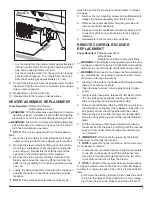
Page 8: ...ance or cleaning to reduce the risk of elec tric shock or damage to persons NOTE This unit is equipped with two flicker motor flicker rod assemblies Determine which motor is defective 1 Open the steel curtains remove glass doors if appli 2 cable on the side where the replacement is required Remove the 2 screws from the log set retaining plate s 3 along the front of the log set on the side where th...

Page 9: ...rient the replacement heater assembly and 7 connect all of the wiring connections in their original locations Reassemble in the reverse order as above 8 Remote Control Receiver Replacement Tools Required Phillips screw driver Wire Cutters Needle Nose Pliers or Slip Joint Pliers Warning If the fireplace was operating prior to servic ing allow at least 10 minutes for light bulbs and heating elements...

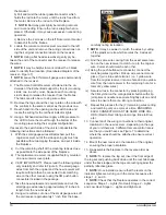
Page 10: ...es from both the original and the new receiver will require cutting to then be connected to its matching wire on the other receiver using the 3M push button connectors included in the package v Take the new replacement receiver plate and cut the small gauge wires leaving approximately 8 inches in length from the new receiver vi Using wire cutters cut one of the small gauge wires off the old receiv...

Page 11: ...N L 1 2 3 4 From Flicker Motor From Lights 2 From Flicker Motor From Lights Switch 3 5 AC1 From Blower From Heater Line In From Blower and Heater From Blower and Heater From Flicker Motor and Lights From Flicker Motor and Lights From Blower and Heater RL1 RL2 RL3 N N L 1 2 4 From Flicker Motor and Lights Switch 3 5 From Heater Line In From Blower and Heater From Flicker Motor and Lights From Blowe...

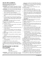
Page 12: ...oming power from the electrical wall socket Check Fuse Breaker Panel Defective On Off Switch Replace On Off Switch Defective Remote Control Receiver Replace Remote Control Receiver Initialize with Re mote Control Fireplace does not turn on in Remote Mode Improper operation Refer to Operation Section Remote control not initialized to fireplace Initialize the remote control Loose wiring Check wiring...

Page 13: ...ation Defective Heater Assembly Replace Heater Assembly Heater fan turns on but heater lacks heat Improper operation Refer to Operation Section Loose wiring Trace wiring in unit Defective Heater Assembly Replace Heater Assembly Heating element is glowing red Normal Operation Small glowing sections of the element are considered normal Defective heater assembly If larger glowing sections are causing...

Reviews: