background image

10 

            www.dimplex.com

ing so that they will not be pinched when re-attaching 

the bottom panel.

14. Insert new bulbs.
15. Re-assemble the firebox in reverse order.

!

 NOTE:

 Ensure the rear tab/ledge on the log-set/ember-

bed is installed tightly under the bottom of the partially 

reflective glass to prevent light leakage.

MOD B

Tools required:

  Phillips head screw driver

Small wire cutter

  CAUTION: 

Follow “Preparation for Service” instructions 

before proceeding.
1.  Carefully turn the firebox onto its back so that the bot-

tom can be easily accessed.

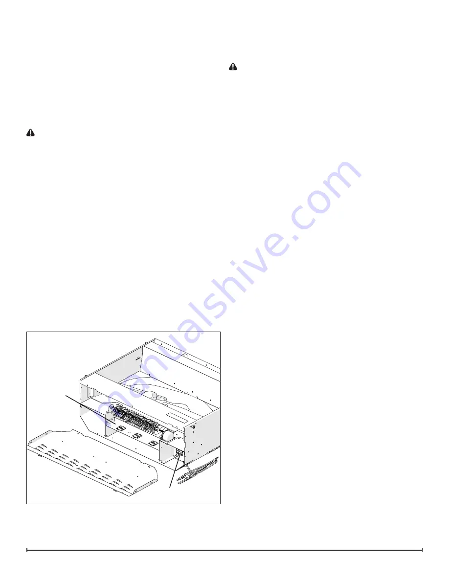
2.  Remove the 9 screws that attach the bottom panel to 

the side panels, 2 on the back side, 2 on the left side, 

2 on the right side and 3 on the bottom along the front 

edge. (Figure 7)

3.  Locate the LED light assembly and remove the 4 

screws securing the assembly to the two side panels.

4.  Remove the light assembly wire ends out of the termi-

nal block by removing the small Philips head screw in 

the 2 respective terminals.

5.  Insert the wire ends from the new light assembly into 

the terminal block following the same orientation of the 

original wires.

6.  Install the new LED light assembly back into the unit.
7.  Re-assemble the firebox in reverse order.

!

 NOTE:

 Ensure that when reinstalling the bottom panel 

of the firebox that no wires are pinched.

FLICKER MOTOR/FLICKER ROD 

REPLACEMENT

Tools Required:

  Phillips head screw driver

  CAUTION: 

Follow “Preparation for Service” instructions 

before proceeding.
1.  Slightly wedge your fingers between the back partially 

reflective glass and the log-set/ember-bed on either 

the right or left side.  Pull the back edge of the plastic 

ember bed forward until the rear tab/ledge clears past 

the bottom of the partially reflective glass and pull the 

log set forward and out.

!

  IMPORTANT:  

Only handle the log-set by the plastic 

ember-bed, not the logs themselves.

!

  NOTE:

 Log-set fits tightly into firebox.  Some force 

may be necessary to remove.

!

  NOTE:

  If your model has the media tray with the 

decorative glass pieces as an ember bed, remove the glass 

pieces then remove the plastic media tray following the 

same method as the log set removal instructions.
2.  Set log set or media tray aside in a safe location.
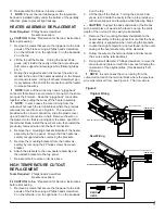
3.  Disconnect flicker rod from the motor by slightly bend-

ing the flicker rod and pulling the rubber gasket off the 

motor shaft. (Figure 3).

!

  NOTE:

 Be careful not to bend the rod.  Doing so may 

damage the rod.  Ensure the rod is straight after re-instal-

lation so that it doesn’t affect the operation of the flicker 

effect.
4.  Carefully turn the firebox upside down so that the bot-

tom panel is facing up.

5.  Remove the 9 screws that attach the bottom panel to 

the side panels, 2 on the back side, 2 on the left side, 

2 on the right side and 3 on the bottom along the front 

edge.

6.  Remove the 3 flicker motor wire ends out of the termi-

nal block by removing the small Philips head screw in 

the 3 respective terminals.  Take note of their location 

on the terminal block.

!

  NOTE:  

A capacitor is also connected in 2 of the 3 

terminals that hold the flicker motor wires on the terminal 

block.   Take note of the terminal locations and the wire 

configuration. 
7.  Using a Philips screwdriver (a short screwdriver is 

recommended), remove the 2 screws holding the flicker 

motor to the mounting brackets. One screw on either 

side and remove the flicker motor out of the housing.  

Take note of the orientation on the brackets.

8.  Place the new motor into the housing and attach the 

motor to the brackets using the 2 Philips screws.

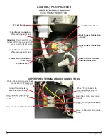
9.  Insert the 3 wire ends from the new flicker motor as 

well as the 2 wires from the original capacitor into the 

terminal block following the orientation of the original 

motor & capacitor. (See Assembly Part Pictures)

10. Tighten terminal screws to secure wires in place.

Figure 7

LED Light 

Assembly

Terminal Block

Summary of Contents for BF9000

Page 1: ...Cambridge ON Canada N1R 7G8 1 888 346 7539 www dimplex com REV PCN DATE 00 22 JUL 11 01 26 AUG 11 02 13118 13 DEC 11 03 31 JAN 14 IMPORTANT SAFETY INFORMATION Always read this manual first before atte...

Page 2: ...Exploded Parts Diagram BF9000 6907560100 7 Wiring Diagram BF9000 6907560100 8 Preparation for Service 9 Light Assembly Replacement 9 MOD 0 A 9 MOD B 10 Flicker Motor Flicker Rod Replacement 10 Heater...

Page 3: ...ation In this position the built in remote control is by passed The position is for operating the unit with the provided remote control When in remote control position the unit is operated with the On...

Page 4: ...bottom of the partially reflective glass IMPORTANT Only handle the log set by the ember bed NOTE Log set fits tightly into firebox some force may be necessary to remove 3 Set Log Set Media Tray in fro...

Page 5: ...2 Flicker Rod 5901110100RP 13 Partially Reflective Glass DF2426 5901410100RP DF2550 DFG2562 5901410200RP 14 Control Knob 8801080100RP 15 DF2426SS Stainless Steel Trim Assembly comes with Front Glass 1...

Page 6: ...DIAGRAM DF2426 DF2550 DFG2562 6905050100 500 MOD 0 A MOD B LED DRIVER BOARD MANUAL CAPACITOR HEATER ON OFF CORD SET ON OFF REMOTE BLOWER HEATER ASSEMBLY FLICKER MOTOR THERMOSTAT OFF REMOTE N SWITCH O...

Page 7: ...on Switch 2800071100RP 9 Remote Control Receiver 3000380200RP 10 Terminal Block 4000150100RP 11 Power Cord 4100040300RP 12 Flicker Rod 5901110100RP 13 Partially Reflective Glass 5901410100RP 14 Contro...

Page 8: ...CAPACITOR HEATER ON OFF CORD SET ON OFF REMOTE BLOWER HEATER ASSEMBLY FLICKER MOTOR THERMOSTAT OFF REMOTE MANUAL CAPACITOR HEATER ON OFF CORD SET ON OFF REMOTE BLOWER HEATER ASSEMBLY FLICKER MOTOR THE...

Page 9: ...set by the plastic ember bed not the logs themselves NOTE Log set fits tightly into firebox Some force may be necessary to remove NOTE If your model has the media tray with the decorative glass pieces...

Page 10: ...ic ember bed not the logs themselves NOTE Log set fits tightly into firebox Some force may be necessary to remove NOTE If your model has the media tray with the decorative glass pieces as an ember bed...

Page 11: ...embly to the top panel Ensure that the heater as sembly is supported when removing the brackets 5 Remove the mounting brackets from the heater as sembly by removing the 2 Philips screws from each brac...

Page 12: ...ilips head screwdriver 2 on the left side 2 on the right side 3 on the backside 2 on the top 2 Lift the top panel up off the firebox turn it 45 degrees and rest it inside the upper cavity against the...

Page 13: ...ginal location of each wire con nected to the board remove each wire and connect then onto the same location on the new log driver board NOTE Using a flat head screwdriver gently pry between the end o...

Page 14: ...ight Harness Connection Neutral Light Harness Connection Live Flicker Motor Connection White with capacitor wire Flicker Motor Connection White with capacitor wire White Connects to a piggy back conne...

Page 15: ...lock Jumper to Piggy Back connection on lower prong of element White Connects to Terminal Block White Jumper to Blower Motor Yellow Connects to Thermostat Grey Connects to High Temperature Cutout on T...

Page 16: ...nection on Outside Prong on Heater On Off Switch JP3 White from upper terminal block JP3 White Piggy Back from lower electrical housing Thermostat Dial Heater Switch O Off On 3 Position Switch Remote...

Page 17: ...per operation Refer to Operation Section No incoming power from the electrical wall socket Check fuse breaker panel Defective 3 Position Switch Replace 3 Position Switch Defective Remote Control Recei...

Page 18: ...ation Defective Heater Assembly Replace Heater Assembly Heater fan turns on but heater lacks heat Improper operation Refer to Operation Section Loose wiring Trace wiring in unit Defective Thermostat R...

Reviews: