


11
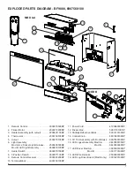
11. Re-assemble the firebox in reverse order.
!
NOTE:
Ensure the rear tab/ledge on the log-set/em-
ber-bed is installed tightly under the bottom of the partially
reflective glass to prevent light leakage.
HEATER ASSEMBLY REPLACEMENT
Tools Required:
Philips head screwdriver
Needle nose pliers
CAUTION:
Follow “Preparation for Service” instructions
before proceeding.
1. Remove 9 screws that secure the top panel to the side
panels of the firebox using a Philips head screwdriver,
2 on the left side; 2 on the right side; 3 on the backside;
2 on the top.
2. Lift the top off the firebox. Turning the panel 45 de-
grees, rest it inside the cavity at the top to provide you
with some support and leverage while following Steps
4 & 5.
3. Noting their original location, disconnect the wires at-
tached to the end of the heater assembly on the blower
motor and element. Using a flat head screwdriver gen-
tly pry between the end of the connector and the heater
to release the wires
!
NOTE:
Some of the wires may have a “piggy-back”
connector that allows a second wire to connect to the same
prong as the first wire. Keep the “piggy-back” connection
together when pulling the wires off the heater assembly.
!
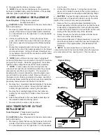
NOTE:
In some cases the wire running from the
cutout will not reach the terminal block where the previous
wire was removed from, see Figure 8. The new wire is
provided with an insert connection, slide the plastic cover
up and bend the connection in half. Remove the wire on
the blower motor, that is running from the same spot off of
the terminal block, install the new bent wire, then install the
previously removed wire onto the bent connection.
4. Remove the 2 mounting brackets that attach the heater
assembly to the top panel. Ensure that the heater as-
sembly is supported when removing the brackets.
5. Remove the mounting brackets from the heater as-
sembly by removing the 2 Philips screws from each
bracket.
6. Attach the brackets to the new heater assembly and
then attach brackets to the top panel.
7. Re-assemble in reverse order as above.
HIGH TEMPERATURE CUTOUT
REPLACEMENT
Tools Required:
Philips head screwdriver
Needle nose pliers
CAUTION:
Follow “Preparation for Service” instructions
before proceeding.
1. Remove 9 screws that secure the top panel to the side
panels of the firebox using a Philips head screwdriver,
2 on the left side; 2 on the right side; 3 on the backside;
2 on the top.
2. Lift the top off the firebox. Turning the panel 45 de-
grees, rest it inside the cavity in the top to provide you
with some support and leverage while following Step 4.
CAUTION:
Support the back underside of the firebox
with a small piece of wood as the feet do not go the entire
depth of the unit and it can easily tip backwards.
3. Remove the 2 mounting brackets that attach to the
heater assembly to the top panel. Ensure that the heat-
er assembly is supported when removing the brackets.
4. Locate the High Temperature Cutout found on the outer
casing of the heater assembly at the elements.
5. Follow the wires to the terminal block and disconnect
the 2 wires at the terminal block.
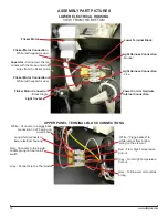
6. Using a small diameter, Philips screwdriver, remove the
old cutout and replace it with the new one following the
orientation of the original wires. (See Assembly Part
Pictures)
!
NOTE:
In some cases the wire running from the
cutout will not reach the terminal block where the previous
wire was removed from, see Figure 8. The new wire is
SHORT CONNECTION
BLOWER HEATER ASSEMBLY
TERMINAL BLOCK
ENSURE WIRE IS ROUTED AROUND BLOWER
TERMINAL BLOCK
BLOWER HEATER ASSEMBLY
Figure 8
BEND
HERE
Original Wiring
New Wiring


