


12
www.dimplex.com
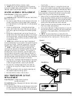
provided with an insert connection, slide the plastic cover
up and bend the connection in half. Remove the wire on
the blower motor, that is running from the same spot off of
the terminal block, install the new bent wire, then install the
previously removed wire onto the bent connection.
7. Re-assemble in reverse order as described above.
3-POSITION OR HEATER SWITCH
REPLACEMENT
Tools Required:
Philips head screwdriver
Needle nose pliers
CAUTION:
Follow “Preparation for Service” instructions
before proceeding.
1. Remove 9 screws that secure the top panel to the side
panels of the firebox using a Philips head screwdriver,
2 on the left side; 2 on the right side; 3 on the backside;
2 on the top.
2. Lift the top panel up off the firebox, turn it 45 degrees
and rest it inside the upper cavity against the back
panel.
CAUTION:
Support the back underside of the firebox
with a small piece of wood as the feet do not go the entire
depth of the unit and it can easily tip backwards.
3. The switch housing panel spans across the front of the
fireplace, near the top. Remove the 6 screws from the
side panels that hold this front panel in place, 3 on the
left and 3 on the right side.
4. Lift the switch-housing panel up and flip it 180 degrees
towards you to expose the wires connected to the
backside of the switch.
5. Taking note of the original location of each wire con-
nected to the switch that needs replacing, (either the
3-Position or the Heater Switch) remove the wires.
!
NOTE:
Using a flat head screwdriver gently pry be-
tween the end of the connector and the switch to release
the wires.
6. Noting the orientation of the switches - the markings
on the face, depress the tabs that secure the switch to
the housing from behind the panel and push the switch
out to the front. Using needle nosed pliers will give you
a better grip and fit to depress both these tabs at the
same time.
7. Push the new switch in place, ensuring that both tabs
are engaged.
8. Re-assemble in reverse order as described above.
THERMOSTAT REPLACEMENT
Tools Required: Philips head screwdriver
CAUTION:
Follow “Preparation for Service” instructions
before proceeding.
1. Remove 9 screws that secure the top panel to the side
panels of the firebox using a Philips head screwdriver,
2 on the left side; 2 on the right side; 3 on the backside;
2 on the top.
2. Lift the top panel up off the firebox, turn it 45 degrees
and rest it inside the upper cavity against the back
panel.
CAUTION:
Support the back underside of the firebox
with a small piece of wood as the feet do not go the entire
depth of the unit and it can easily tip backwards.
3. On the front face of the switch housing, remove the 2
screws that hold the thermostat to the panel.
4. The switch housing panel spans across the entire top
on the front of the fireplace. Remove the 6 screws
from the side panels that hold this front panel in place,
3 on the left and 3 on the right side.
5. Lift the switch-housing panel up and flip it 180 degrees
towards you to expose the wires connected to the
backside of the thermostat.
6. Remove the dial off the control shaft by pulling forward
away from the thermostat.
!
NOTE:
Note that the dial will only go back on the shaft
one way when replacing.
7. Remove thermostat from the mounting bracket by re-
moving the 2 Philips screws located on the bracket.
8. Taking note of the original location of each wire con-
nected to the thermostat remove the wires and place
onto the new thermostat.
!
NOTE:
Using a flat head screwdriver gently pry
between the end of the connector and the thermostat to
release the wires.
9. Re-assemble in reverse order as described above.
REMOTE CONTROL RECEIVER
REPLACEMENT
Tools Required:
Philips head screwdriver
Needle nose pliers
Small cutter or snips
CAUTION:
Follow “Preparation for Service” instructions
before proceeding.
1. Remove 9 screws that secure the top panel to the side
panels of the firebox using a Philips head screwdriver,
2 on the left side; 2 on the right side; 3 on the backside;
2 on the top.
2. Lift the top panel up off the firebox, turn it 45 degrees
and rest it inside the upper cavity against the back
panel.
CAUTION:
Support the back underside of the firebox
with a small piece of wood as the feet do not go the entire
depth of the unit and it can easily tip backwards.
3. The switch housing panel spans across the entire top
on the front of the fireplace. Remove the 6 screws
from the side panels that hold this front panel in place,
3 on the left and 3 on the right side.
4. Lift up the switch-housing panel and carefully rest it
inside the upper cavity.
5. Taking note of the original location of each wire con-
nected to the board, remove each wire and connect


