background image

2             www.dimplex.com

Always use a qualified technician or service agency to repair this fireplace.

!

 NOTE: 

 Procedures and techniques that are considered important enough to emphasize.

 CAUTION:

  Procedures and techniques which, if not carefully followed, will result in damage to the 

equipment.


WARNING:

  Procedures and techniques which, if not carefully followed, will expose the user to the 

risk of fire, serious injury, or death.

Operation   .  .  .  .  .  .  .  .  .  .  .  .  .  .  .  .  .  .  .  .  .  .  .  .  .  .  .  .  .  .  .  .  .  .  .  .  .  .  .  .  .  .  .  .  .  .  .  .  .  .  .  .  .  .  .  .  .  .  . 3
Maintenance  .  .  .  .  .  .  .  .  .  .  .  .  .  .  .  .  .  .  .  .  .  .  .  .  .  .  .  .  .  .  .  .  .  .  .  .  .  .  .  .  .  .  .  .  .  .  .  .  .  .  .  .  .  .  .  .  . 4
Exploded Parts Diagram: DF2426, DF2550, DFG2562, 6905050100-500    .  .  .  .  .  .  .  . 5
Wiring Diagram: DF2426, DF2550, DFG2562, 6905050100-500   .  .  .  .  .  .  .  .  .  .  .  .  .  .  .  . 6
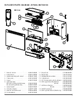
Exploded Parts Diagram - BF9000, 6907560100  .  .  .  .  .  .  .  .  .  .  .  .  .  .  .  .  .  .  .  .  .  .  .  .  .  .  .  . 7
Wiring Diagram - BF9000, 6907560100   .  .  .  .  .  .  .  .  .  .  .  .  .  .  .  .  .  .  .  .  .  .  .  .  .  .  .  .  .  .  .  .  .  .  . 8
Preparation for Service  .  .  .  .  .  .  .  .  .  .  .  .  .  .  .  .  .  .  .  .  .  .  .  .  .  .  .  .  .  .  .  .  .  .  .  .  .  .  .  .  .  .  .  .  .  .  .  . 9
Light Assembly Replacement    .  .  .  .  .  .  .  .  .  .  .  .  .  .  .  .  .  .  .  .  .  .  .  .  .  .  .  .  .  .  .  .  .  .  .  .  .  .  .  .  .  . 9

MOD 0-A   .  .  .  .  .  .  .  .  .  .  .  .  .  .  .  .  .  .  .  .  .  .  .  .  .  .  .  .  .  .  .  .  .  .  .  .  .  .  .  .  .  .  .  .  .  .  .  .  .  .  .  .  .  .  .  .  .  .  .  .  .  .  .  .  .  .  .  .  . 9

MOD B   .  .  .  .  .  .  .  .  .  .  .  .  .  .  .  .  .  .  .  .  .  .  .  .  .  .  .  .  .  .  .  .  .  .  .  .  .  .  .  .  .  .  .  .  .  .  .  .  .  .  .  .  .  .  .  .  .  .  .  .  .  .  .  .  .  .  .  .  .  . 10

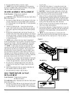
Flicker Motor/Flicker Rod Replacement   .  .  .  .  .  .  .  .  .  .  .  .  .  .  .  .  .  .  .  .  .  .  .  .  .  .  .  .  .  .  .  .  . 10
Heater Assembly Replacement    .  .  .  .  .  .  .  .  .  .  .  .  .  .  .  .  .  .  .  .  .  .  .  .  .  .  .  .  .  .  .  .  .  .  .  .  .  .  .  . 11
High Temperature Cutout Replacement   .  .  .  .  .  .  .  .  .  .  .  .  .  .  .  .  .  .  .  .  .  .  .  .  .  .  .  .  .  .  .  .  . 11
3-Position or Heater Switch Replacement    .  .  .  .  .  .  .  .  .  .  .  .  .  .  .  .  .  .  .  .  .  .  .  .  .  .  .  .  .  .  . 12
Thermostat replacement  .  .  .  .  .  .  .  .  .  .  .  .  .  .  .  .  .  .  .  .  .  .  .  .  .  .  .  .  .  .  .  .  .  .  .  .  .  .  .  .  .  .  .  .  .  . 12
Remote Control Receiver Replacement    .  .  .  .  .  .  .  .  .  .  .  .  .  .  .  .  .  .  .  .  .  .  .  .  .  .  .  .  .  .  .  .  . 12
LED Log Driver Replacement  .  .  .  .  .  .  .  .  .  .  .  .  .  .  .  .  .  .  .  .  .  .  .  .  .  .  .  .  .  .  .  .  .  .  .  .  .  .  .  .  .  . 13
Power Cord Replacement  .  .  .  .  .  .  .  .  .  .  .  .  .  .  .  .  .  .  .  .  .  .  .  .  .  .  .  .  .  .  .  .  .  .  .  .  .  .  .  .  .  .  .  .  . 13
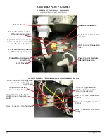
Assembly Part Pictures    .  .  .  .  .  .  .  .  .  .  .  .  .  .  .  .  .  .  .  .  .  .  .  .  .  .  .  .  .  .  .  .  .  .  .  .  .  .  .  .  .  .  .  .  .  . 14

LOWER ELECTRICAL HOUSING     .  .  .  .  .  .  .  .  .  .  .  .  .  .  .  .  .  .  .  .  .  .  .  .  .  .  .  .  .  .  .  .  .  .  .  .  .  .  .  .  .  .  .  .  .  .  . 14

UPPER PANEL TERMINAL BLOCK CONNECTIONS    .  .  .  .  .  .  .  .  .  .  .  .  .  .  .  .  .  .  .  .  .  .  .  .  .  .  .  .  .  .  .  . 14

HEATER ASSEMBLY CONNECTIONS   .  .  .  .  .  .  .  .  .  .  .  .  .  .  .  .  .  .  .  .  .  .  .  .  .  .  .  .  .  .  .  .  .  .  .  .  .  .  .  .  .  .  .  . 15

HEATER ASSEMBLY CONNECTIONS WITH HIGH TEMPERATURE CUTOUT   .  .  .  .  .  .  .  .  .  .  .  . 15

REMOTE CONTROL RECEIVER BOARD CONNECTIONS  .  .  .  .  .  .  .  .  .  .  .  .  .  .  .  .  .  .  .  .  .  .  .  .  .  .  .  . 16

THERMOSTAT DIAL, HEATER AND 3-POSITION SWITCHES   .  .  .  .  .  .  .  .  .  .  .  .  .  .  .  .  .  .  .  .  .  .  .  .  . 16

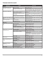
Troubleshooting Guide   .  .  .  .  .  .  .  .  .  .  .  .  .  .  .  .  .  .  .  .  .  .  .  .  .  .  .  .  .  .  .  .  .  .  .  .  .  .  .  .  .  .  .  .  .  .  . 17

TABLE OF CONTENTS

Summary of Contents for BF9000

Page 1: ...Cambridge ON Canada N1R 7G8 1 888 346 7539 www dimplex com REV PCN DATE 00 22 JUL 11 01 26 AUG 11 02 13118 13 DEC 11 03 31 JAN 14 IMPORTANT SAFETY INFORMATION Always read this manual first before atte...

Page 2: ...Exploded Parts Diagram BF9000 6907560100 7 Wiring Diagram BF9000 6907560100 8 Preparation for Service 9 Light Assembly Replacement 9 MOD 0 A 9 MOD B 10 Flicker Motor Flicker Rod Replacement 10 Heater...

Page 3: ...ation In this position the built in remote control is by passed The position is for operating the unit with the provided remote control When in remote control position the unit is operated with the On...

Page 4: ...bottom of the partially reflective glass IMPORTANT Only handle the log set by the ember bed NOTE Log set fits tightly into firebox some force may be necessary to remove 3 Set Log Set Media Tray in fro...

Page 5: ...2 Flicker Rod 5901110100RP 13 Partially Reflective Glass DF2426 5901410100RP DF2550 DFG2562 5901410200RP 14 Control Knob 8801080100RP 15 DF2426SS Stainless Steel Trim Assembly comes with Front Glass 1...

Page 6: ...DIAGRAM DF2426 DF2550 DFG2562 6905050100 500 MOD 0 A MOD B LED DRIVER BOARD MANUAL CAPACITOR HEATER ON OFF CORD SET ON OFF REMOTE BLOWER HEATER ASSEMBLY FLICKER MOTOR THERMOSTAT OFF REMOTE N SWITCH O...

Page 7: ...on Switch 2800071100RP 9 Remote Control Receiver 3000380200RP 10 Terminal Block 4000150100RP 11 Power Cord 4100040300RP 12 Flicker Rod 5901110100RP 13 Partially Reflective Glass 5901410100RP 14 Contro...

Page 8: ...CAPACITOR HEATER ON OFF CORD SET ON OFF REMOTE BLOWER HEATER ASSEMBLY FLICKER MOTOR THERMOSTAT OFF REMOTE MANUAL CAPACITOR HEATER ON OFF CORD SET ON OFF REMOTE BLOWER HEATER ASSEMBLY FLICKER MOTOR THE...

Page 9: ...set by the plastic ember bed not the logs themselves NOTE Log set fits tightly into firebox Some force may be necessary to remove NOTE If your model has the media tray with the decorative glass pieces...

Page 10: ...ic ember bed not the logs themselves NOTE Log set fits tightly into firebox Some force may be necessary to remove NOTE If your model has the media tray with the decorative glass pieces as an ember bed...

Page 11: ...embly to the top panel Ensure that the heater as sembly is supported when removing the brackets 5 Remove the mounting brackets from the heater as sembly by removing the 2 Philips screws from each brac...

Page 12: ...ilips head screwdriver 2 on the left side 2 on the right side 3 on the backside 2 on the top 2 Lift the top panel up off the firebox turn it 45 degrees and rest it inside the upper cavity against the...

Page 13: ...ginal location of each wire con nected to the board remove each wire and connect then onto the same location on the new log driver board NOTE Using a flat head screwdriver gently pry between the end o...

Page 14: ...ight Harness Connection Neutral Light Harness Connection Live Flicker Motor Connection White with capacitor wire Flicker Motor Connection White with capacitor wire White Connects to a piggy back conne...

Page 15: ...lock Jumper to Piggy Back connection on lower prong of element White Connects to Terminal Block White Jumper to Blower Motor Yellow Connects to Thermostat Grey Connects to High Temperature Cutout on T...

Page 16: ...nection on Outside Prong on Heater On Off Switch JP3 White from upper terminal block JP3 White Piggy Back from lower electrical housing Thermostat Dial Heater Switch O Off On 3 Position Switch Remote...

Page 17: ...per operation Refer to Operation Section No incoming power from the electrical wall socket Check fuse breaker panel Defective 3 Position Switch Replace 3 Position Switch Defective Remote Control Recei...

Page 18: ...ation Defective Heater Assembly Replace Heater Assembly Heater fan turns on but heater lacks heat Improper operation Refer to Operation Section Loose wiring Trace wiring in unit Defective Thermostat R...

Reviews: