background image

3

the remote casing and battery cover (Figure 2).

!

 NOTE:

  The remote control is an EEPROM system; 

therefore if power is interrupted for whatever reason, 

the built-in receiver board will hold the memory of 

the remote’s radio frequency for up to 24 hours.  The 

remote should continue to operate the fireplace as 

normal once unit is re-powered.  Re-initialization of the 

remote control to the fireplace should only be required 

if there is a loss of power to the receiver for longer than 

24 hours. (i.e. power failure, main power switch is turned 

off).

To operate, push the ON button to turn fireplace on, push 

the OFF button to turn the fireplace off.

!

 NOTE

: Ensure that the fireplace 3-Position switch is 

set to the remote control setting .

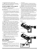
Remote Control Initialization/Reprogramming

If the hand held transmitter or receiver board has been 

replaced, follow these steps to initialize the transmitter and 

receiver:

1.  Place the 

3-Position Switch

 (Figure 1A) in the OFF 

(“O”) position.

2.  Wait a minimum of five (5) seconds and then place the 

3-Position Switch

 in the Remote Control (“=”) position.

3 .  Within

 10 seconds of changing the switch position, 

press the ON button located on the remote control 

(Figure 2). 

This will synchronize the remote control and the fireplace 

receiver.

!

 NOTE: 

You will have only 10 seconds to perform this 

last step. Failure to do so will result in these steps 

needing to be followed again.

Battery Replacement 

To replace the battery:

1.  Slide battery cover open on the remote control  

(Figure 2).

2.  Install one (1) 12-Volt (A23) battery in the battery 

holder.

3.  Close the battery cover

Battery must be recycled or disposed of properly. 

Check with your Local Authority or Retailer for 

recycling advice in your area.
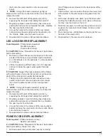
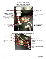
OPERATION

A . 3-Position Switch

The switch has two On positions marked.  The “ -- “ position 

is for manual operation.  In this position the built-in remote 

control is by-passed.  The “ = “ position is for operating 

the unit with the provided remote control.  When in remote 

control (“ = “) position the unit is operated with the On and 

Off buttons of the remote control. 
When the switch is in the center “o” position the unit is off.

B . Heater Switch

The Heater Switch supplies power to the heater fan and the 

heater element.  When the switch is in the ON position the 

heater operates if the thermostat calls for heat.

C . Heater Thermostat Control

To adjust the temperature to your individual requirements, 

turn the thermostat control clockwise all the way to 

turn on the heater. When the room reaches the desired 

temperature, turn the thermostat knob counter-clockwise 

until you hear a click. Leave in this position to maintain the 

room temperature at this setting. For additional heat, turn 

clockwise until you hear the click again and the heater will 

turn on.

Resetting the Temperature Cutoff Switch

Should the heater overheat, an automatic cut out will turn 

the fireplace off and it will not come back on without being 

reset.  It can be reset by switching the 3-Position Switch to 

Off and waiting five (5) minutes before switching the unit 

back on.

!

  NOTE: 

 If operating the unit with a remote control, the 

remote may require re-initializing after turning the power 

off.

 CAUTION:  

If you need to continuously reset the heater, 

disconnect power and call Dimplex customer service at 

1-888-DIMPLEX (1-888-346-7539).

Remote Control

The fireplace is supplied with a radio frequency remote 

control.  This remote control has a range of approximately 

50 feet (15.25 m), it does not have to be pointed at the 

fireplace and can pass through most obstacles (including 

walls).  It is supplied with one of hundreds of independent 

frequencies to prevent interference with other units.

!

 NOTE: 

 Before attempting any operation with the 

remote, pull the plastic insulator strip out from between 

Figure 2

Off Button

On 

Button

Battery 

Cover

Plastic 

Strip

Figure 1

A

B

C

Summary of Contents for BF9000

Page 1: ...Cambridge ON Canada N1R 7G8 1 888 346 7539 www dimplex com REV PCN DATE 00 22 JUL 11 01 26 AUG 11 02 13118 13 DEC 11 03 31 JAN 14 IMPORTANT SAFETY INFORMATION Always read this manual first before atte...

Page 2: ...Exploded Parts Diagram BF9000 6907560100 7 Wiring Diagram BF9000 6907560100 8 Preparation for Service 9 Light Assembly Replacement 9 MOD 0 A 9 MOD B 10 Flicker Motor Flicker Rod Replacement 10 Heater...

Page 3: ...ation In this position the built in remote control is by passed The position is for operating the unit with the provided remote control When in remote control position the unit is operated with the On...

Page 4: ...bottom of the partially reflective glass IMPORTANT Only handle the log set by the ember bed NOTE Log set fits tightly into firebox some force may be necessary to remove 3 Set Log Set Media Tray in fro...

Page 5: ...2 Flicker Rod 5901110100RP 13 Partially Reflective Glass DF2426 5901410100RP DF2550 DFG2562 5901410200RP 14 Control Knob 8801080100RP 15 DF2426SS Stainless Steel Trim Assembly comes with Front Glass 1...

Page 6: ...DIAGRAM DF2426 DF2550 DFG2562 6905050100 500 MOD 0 A MOD B LED DRIVER BOARD MANUAL CAPACITOR HEATER ON OFF CORD SET ON OFF REMOTE BLOWER HEATER ASSEMBLY FLICKER MOTOR THERMOSTAT OFF REMOTE N SWITCH O...

Page 7: ...on Switch 2800071100RP 9 Remote Control Receiver 3000380200RP 10 Terminal Block 4000150100RP 11 Power Cord 4100040300RP 12 Flicker Rod 5901110100RP 13 Partially Reflective Glass 5901410100RP 14 Contro...

Page 8: ...CAPACITOR HEATER ON OFF CORD SET ON OFF REMOTE BLOWER HEATER ASSEMBLY FLICKER MOTOR THERMOSTAT OFF REMOTE MANUAL CAPACITOR HEATER ON OFF CORD SET ON OFF REMOTE BLOWER HEATER ASSEMBLY FLICKER MOTOR THE...

Page 9: ...set by the plastic ember bed not the logs themselves NOTE Log set fits tightly into firebox Some force may be necessary to remove NOTE If your model has the media tray with the decorative glass pieces...

Page 10: ...ic ember bed not the logs themselves NOTE Log set fits tightly into firebox Some force may be necessary to remove NOTE If your model has the media tray with the decorative glass pieces as an ember bed...

Page 11: ...embly to the top panel Ensure that the heater as sembly is supported when removing the brackets 5 Remove the mounting brackets from the heater as sembly by removing the 2 Philips screws from each brac...

Page 12: ...ilips head screwdriver 2 on the left side 2 on the right side 3 on the backside 2 on the top 2 Lift the top panel up off the firebox turn it 45 degrees and rest it inside the upper cavity against the...

Page 13: ...ginal location of each wire con nected to the board remove each wire and connect then onto the same location on the new log driver board NOTE Using a flat head screwdriver gently pry between the end o...

Page 14: ...ight Harness Connection Neutral Light Harness Connection Live Flicker Motor Connection White with capacitor wire Flicker Motor Connection White with capacitor wire White Connects to a piggy back conne...

Page 15: ...lock Jumper to Piggy Back connection on lower prong of element White Connects to Terminal Block White Jumper to Blower Motor Yellow Connects to Thermostat Grey Connects to High Temperature Cutout on T...

Page 16: ...nection on Outside Prong on Heater On Off Switch JP3 White from upper terminal block JP3 White Piggy Back from lower electrical housing Thermostat Dial Heater Switch O Off On 3 Position Switch Remote...

Page 17: ...per operation Refer to Operation Section No incoming power from the electrical wall socket Check fuse breaker panel Defective 3 Position Switch Replace 3 Position Switch Defective Remote Control Recei...

Page 18: ...ation Defective Heater Assembly Replace Heater Assembly Heater fan turns on but heater lacks heat Improper operation Refer to Operation Section Loose wiring Trace wiring in unit Defective Thermostat R...

Reviews: