


9
PREPARATION FOR SERVICE
CAUTION:
If unit was operating prior to servicing allow
at least 10 minutes for lights, heating elements and top
panel to cool off to avoid accidental burning of skin.
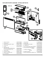
1. Remove the firebox out of the cabinet or wall frame that
surrounds the unit.
2. Disconnect power before attempting any maintenance.
!
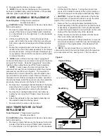
NOTE:
This unit may have been installed to a power
source in one of 2 ways: (SEE FIGURE 5 & 6).
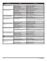
• Option #1 – Plugged into an outlet.
A power cord with plug, inserted into an outlet near
or behind the fireplace, unplug the fireplace from the
outlet.
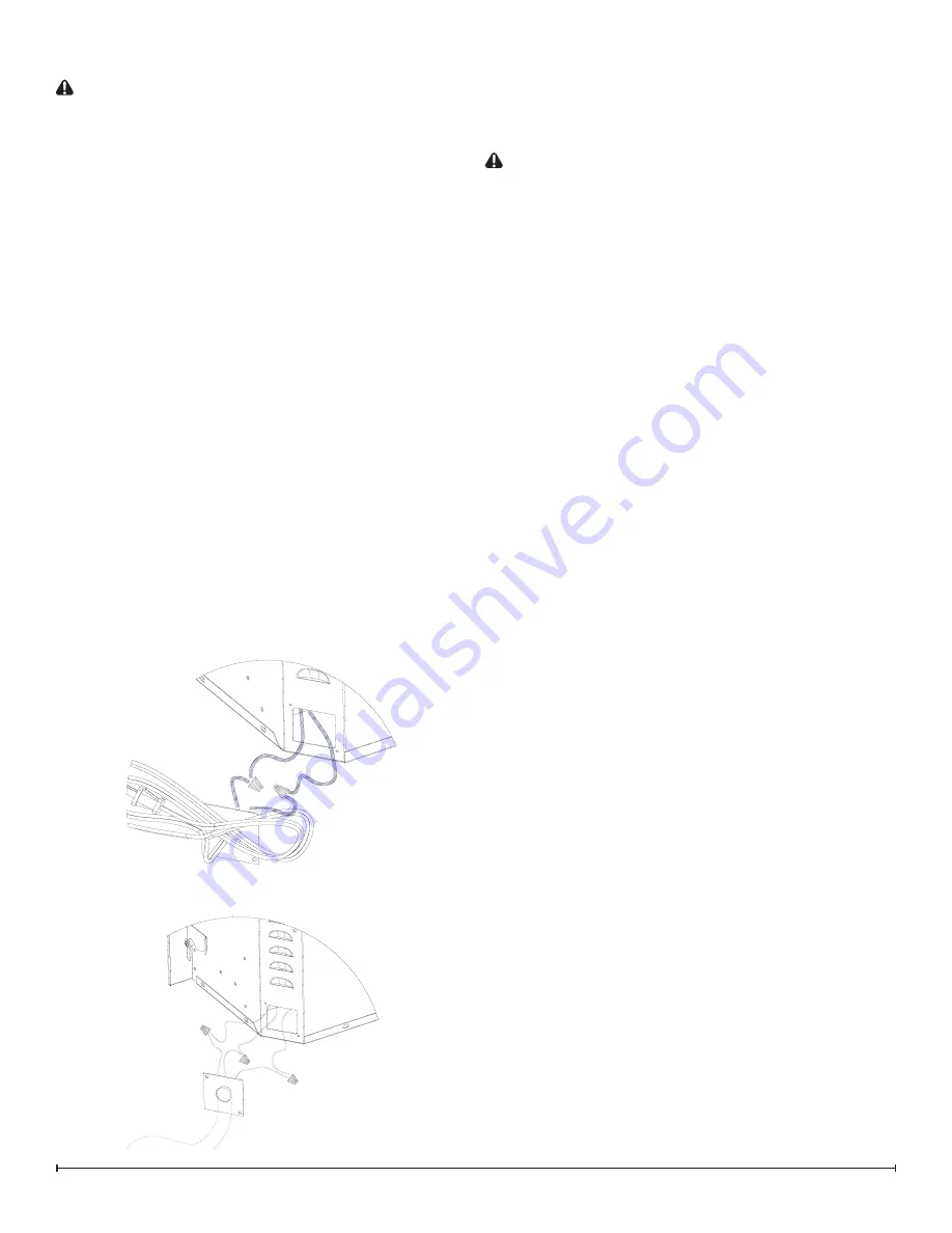
• Option #2 – Hardwire connection.
Power supplied from electrical wire coming from a
dedicated, properly fused circuit with 120 Volt, 15 Amp
rating directly from the main electrical panel, turn the
breaker off at the electrical panel.
• It is recommended during original installation,
there should be an allowance of up to 8 feet of
service cable for connecting power supply to the
junction box on fireplace.
3. Remove the front glass assembly by lifting the front
glass assembly off of the 4 mounts located on the outer
casing of the fireplace 2 on the left and 2 on the right.
Carefully place the glass assembly aside in a safe loca-
tion.
LIGHT ASSEMBLY REPLACEMENT
MOD 0-A
Tools required:
Phillips head screw driver
Small wire cutter
CAUTION:
Follow “Preparation for Service” instructions
before proceeding.
1. Slightly wedge your fingers between the partially reflec-
tive glass and the log-set/ember-bed on either the right
or left side. Pull the back edge of the plastic ember
bed forward until the rear tab/ledge clears past the bot-
tom of the partially reflective glass and pull the log set
forward and out of the unit. (Figure 4).
!
IMPORTANT:
Only handle the log-set by the plastic
ember-bed, not the logs themselves.
!
NOTE:
Log-set fits tightly into firebox. Some force
may be necessary to remove.
!
NOTE:
If your model has the media tray with the
decorative glass pieces as an ember bed, remove the glass
pieces then remove the plastic media tray following the
same method as the log set removal instructions.
2. Set log-set or media bed aside in a safe location.
3. Disconnect the flicker rod from the motor by pulling and
twisting the rubber gasket/connector away from the
motor. This is the gasket which joins the rod and the
motor together. Once separated, pull the flicker rod out
from the bracket and bushing from opposite side, and
remove it from the firebox.
!
NOTE:
Be careful not to bend the rod. Doing so may
damage the rod. Ensure the rod is straight after re-instal-
lation so that it doesn’t affect the operation of the flicker
effect.
4. Carefully turn the firebox upside down so that the bot-
tom panel is facing up.
5. Remove the 9 screws that hold the bottom panel in
place, 2 on the back, 2 on the left, 2 on the right and 3
on the bottom along the front edge.
6. Remove the light bulbs by turning counter clockwise.
7. Remove the rings that hold the sockets to the side
panel by turning/unscrewing the rings counter clock-
wise. Push the sockets out of the panel.
8. Cut the wire ties that are holding the wires to the cas-
ing.
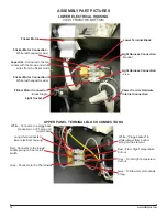
9. Remove the light harness wire ends out of the terminal
block by removing the small Philips head screw in the 2
respective terminals.
10. Insert the wire ends from the new light harness into
the terminal block following the same orientation of the
original harness.
11. Tighten terminal screws to secure wires in place.
12. Insert the new sockets into the opening on the socket
panel on the left and right. Place the ring onto the
socket and tighten to secure the socket into place.
13. Tuck the light harness wires around the light panel/cas-
Figure 5
Figure 6


