background image

www.dimplex.com

Installazione del caminetto


8

www.dimplex.com

Il caminetto è provvisto di una spina 

-)$!+)!+33%)4+!)-5+2&/-!+)%/)#&//+

-

gamento elettrico. Il collegamento 

diretto  rappresenta un‘altra possi-

3%/%$6?)!%."&2+'*&)/-)(4%'-)*-/)#-2&)

4!+4-!-$&)%'):-33!%#-)+)#&.4/+$-'*&)%/)

#-3/-55%&)%')3-(+)-//+)'&!.+)+/+$$!%

-

che nazionali e locali.


AVVERTENZA: 

Non tentare di 

#-3/-!+)'"&2+)4!+(+)&)#%!#"%$%7)J+!)

ridurre il rischio di incendi, scos-

se elettriche e lesioni personali, 

rivolgersi sempre a un elettricista 

8"-/%0#-$&7


AVVERTENZA: 

Assicurarsi 

che l‘interruttore a 3 posizioni sia 

impostato sulla posizione di spento 

(„o“) e che il circuito sul quale 

deve essere installato il caminetto 

-33%-)/i-/%.+'$-@%&'+)%'$+!!&$$-)("/)

4-''+//&)*%)(+!2%@%&)0'&)-/)#&.4/+

-

tamento dell‘installazione.

7#4$%11%83"#'(03(4+9',:;3'


ATTENZIONE: 

J&$!+33+!&)

essere necessarie due persone per 

diversi punti di questa procedura.

V7)e#+5/%+!+)"'i"3%#-@%&'+)4+!)%/).&'

-

taggio dell‘unità.

2. Scegliere il metodo di alimentazio-

ne dell‘unità:

W) Y'(+!%!+)/-)(4%'-)%')"'-)4!+(-)+(%(

-

tente o installare una presa nelle 

vicinanze.

W) h&//+5-!+)*%!+$$-.+'$+)%/)#-.%'+$$&7


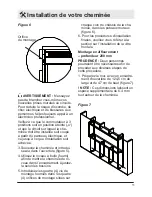
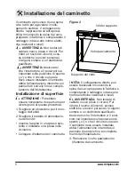
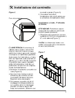
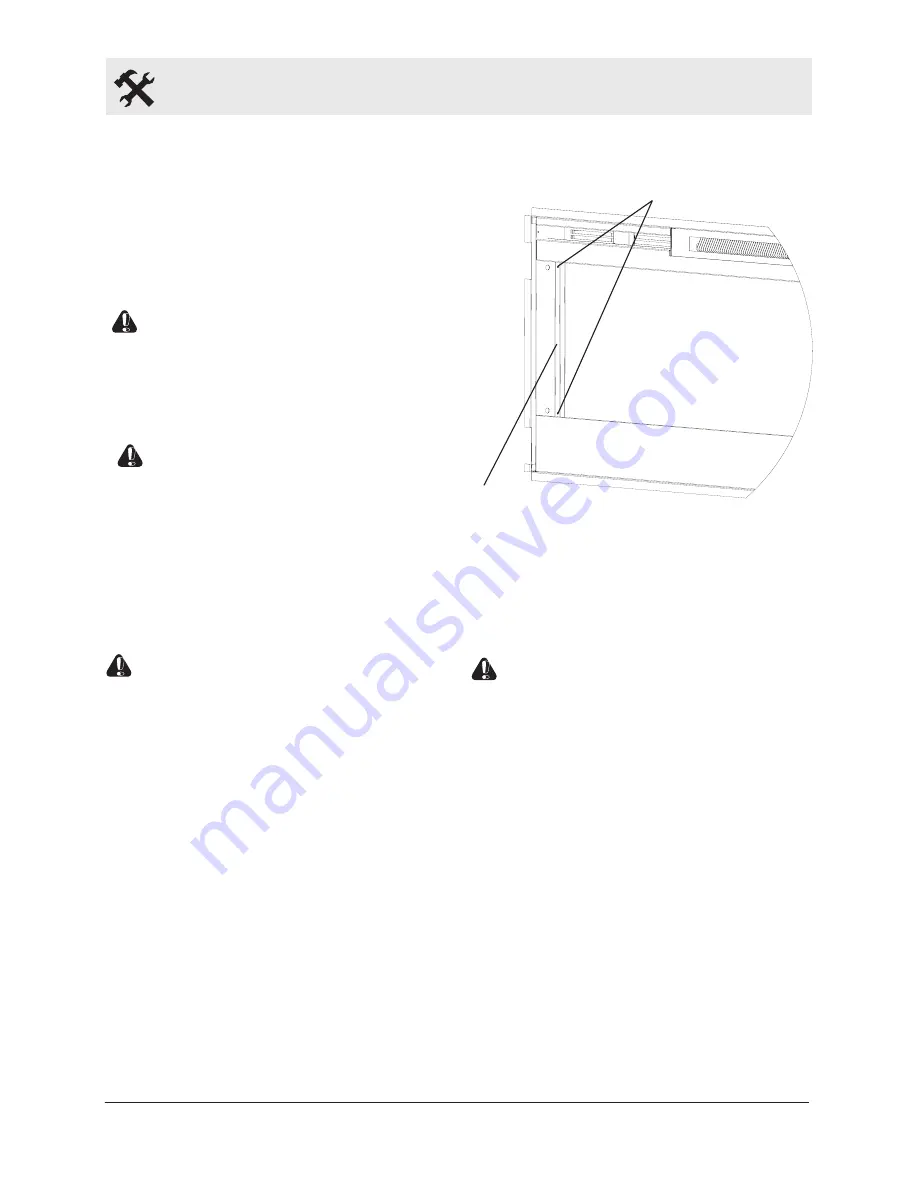
Figura 2

                                Viti del supporto

Vetro parzialmente 

Supporto del vetro

! NOTA:

 Il collegamento diretto può 

essere realizzato rimuovendo la 

(4%'-)*-/)#-2&)4!+4-!-$&)%'):-33!%#-)+)

#&.4/+$-'*&)%/)#-3/-55%&)%')3-(+)-//+)

norme elettriche nazionali e locali

.


AVVERTENZA:

 Non tentare di 

#-3/-!+)'"&2+)4!+(+)&)#%!#"%$%7)J+!)

ridurre il rischio di incendi, scosse 

elettriche e lesioni personali, rivolgersi 

(+.4!+)-)"')+/+$$!%#%($-)8"-/%0#-$&7

Assicurarsi che l‘interruttore a 3 posi-

zioni sia impostato sulla posizione di 

spento („o“) e che il circuito sul quale 

il caminetto deve essere installato 

-33%-)/i-/%.+'$-@%&'+)%'$+!!&$$-)("/)

4-''+//&)*%)(+!2%@%&)0'&)-/)#&.4/+$-

-

mento dell‘installazione.
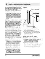
3. Rimuovere il vetro parzialmente 

!%;+$$+'$+)*-/)#-.%'+$$&F

Summary of Contents for BFL50-EU

Page 1: ...7212350100R00 IMPORTANT SAFETY INFORMATION 0 1 2 34 5 6 4 4 0 1 5 7 8 94 40 3 74 5 6 3 07 4 74 0 4 5 5 4 0 4 5 45 6 8 Owner s Manual Mode 9 ABC IT DE FR EN...

Page 2: ...ill result in damage to the equipment WARNING Procedures and techniques which if not carefully followed will expose the user to the risk of fire serious injury or death Welcome Congratulations 3 IMPOR...

Page 3: ...tions CAUTION Read all instructions and warnings carefully before starting installation Failure to follow these instructions may result in a possible electric shock fire hazard and will void the warra...

Page 4: ...er in small rooms when they are occupied by persons not capable of leaving the room on their own unless constant supervision is provided Children of less than 3 years IMPORTANT INSTRUCTIONS should be...

Page 5: ...e Use it only as described in this manual Any other use not recommended by the manufacturer may cause fire electric shock or injury to persons Avoid the use of an extension cord Extension cords may ov...

Page 6: ...efore installation please record your fireplace s serial number below for future reference If you have any technical questions or concerns regarding the operation of your electric fireplace or require...

Page 7: ...lations to reduce the risk of fire electric shock and injury to persons Select a location that is not 1 susceptible to moisture and is away from drapes furniture and high traffic Fireplace Installatio...

Page 8: ...AUTION Two people may be required for various steps of this procedure Choose a location for 1 mounting the unit Choose your method of 2 supplying power to the unit Plug in to an existing outlet or ins...

Page 9: ...t of key holes Tighten all four 4 mounting 9 screws down on fireplace chassis Screw the two 2 supplied 10 8 square head screws through two of the permanent mounting holes which align with a wall stud...

Page 10: ...1 opening of 118 1 cm wide x 42 cm high Figure 4 NOTE The sizing has allowed for 6 4mm around the fireplace insert for ease of installation This fireplace does not require any additional venting Choos...

Page 11: ...omplete Lift fireplace and insert into 3 opening Figure 5 Use bubble level supplied to 4 level the fireplace within the framing Adjust as required Drive four 4 supplied 5 mounting screws through the f...

Page 12: ...3 Position Switch is set to the Off position O and that the circuit on which the fireplace is to be installed has the power cut off at the service panel until installation is complete Lift fireplace...

Page 13: ...ps sheet metal screws to fasten the glass assembly tabs to the fireplace Figure 11 Ensure the fireplace s 4 3 Position Switch is switched to the Off position O If unit is not hard wired plug 5 firepla...

Page 14: ...h supplies power to the heater fan and the heater element Resetting the Temperature Cutoff Switch Should the heater overheat an automatic cut out will turn the fireplace off and it will not come back...

Page 15: ...AAA batteries into the 2 remote control Replace the battery cover 3 Discard leaky batteries Dispose of batteries in the proper manner according to provincial and local regulations Any battery may lea...

Page 16: ...s these can be removed by dusting lightly with a clean dry cloth To remove fingerprints or other marks the partially reflective glass can be cleaned with a damp cloth The partially reflective glass sh...

Page 17: ...of or inability to use the product The warranty will not apply if in the sole judgment of the Company damage or failure has resulted from accident alteration misuse abuse incorrect installation or ope...

Page 18: ...IT IMPORTANTES Lisez attentive ment ce manuel avant d installer ou d utiliser cette chemin e Pour votre s curit respectez toujours tous les AVERTISSEMENTS et inst 0 1 2 3 4 5 6 2 3 7 Manuel de l utili...

Page 19: ...ient exposer l utilisateur un danger d incendie de graves 3 6 8 7 Pour vos r parations faites toujours appel un technicien ou une entreprise 2 8 0 2 Table des mati res Bienvenue et f licitations 3 INS...

Page 20: ...structions PRUDENCE Veuillez lire attentivement toutes ces instructions et aver tissements avant de commencer l installation En cas de non respect de ces 2 4 3 A 8 8 1 annulerez la garantie Veuillez n...

Page 21: ...emp rature de la pi ce Ne l utilisez pas dans des pi ces de petites dimensions lorsqu elles sont occup es par des 4 4 3 1 moins d assurer leur surveillance permanente 6 Les enfants de moins de 3 ans d...

Page 22: ...type d utilisation non 4 3 4 causer un incendie un choc lectrique ou 3 C 4 7 21 vitez d utiliser une rallonge Elle pourrait surchauffer et causer un risque d incendie Si vous en utilisez une elle L 6...

Page 23: ...l derri re la vitre Avant de l installer veuillez noter le 8 3 4 future r f rence 2 Si vous avez des questions ou des 4 3 N A 8 le fonctionnement de votre chemi 8 8 1 3 d tre r par e contactez notre s...

Page 24: ...t les prises lec triques doivent tre conformes aux 3M 2 5 toutes autres r glementations 44 3 7 1 Choisissez un emplacement non expos l humidit et loign de C 3 importante 7 J 4 0 3 A lectrique vous pou...

Page 25: ...tion en surface PRUDENCE Deux personnes 4 L 0 proc der aux diverses tapes de cette proc dure 1 Choisissez l endroit o monter l appareil 2 Choisissez votre m thode d approvisionnement lectrique W Z A 1...

Page 26: ...es chevilles sp ciales et ce qu une au moins soit situ e dans le poteau mural 6 Retirez la chemin e du mur et 5 K D R 4 sonne ne circule 7 Vissez les quatre 4 vis de mon tage t te carr e n 8 de 3 8 cm...

Page 27: ...ent un espace suppl mentaire de 6 4 mm tout autour de la chemin e encast 3 0 1 1 7 Cette chemin e ne n cessite pas de ventilation suppl mentaire 2 Choisissez votre m thode d approvisionnement lectriqu...

Page 28: ...1 2 05 b_7 c7 H 2 6 3 _ 0 A veau dans l encadrement Ajustez 3 7 5 Introduisez les quatre 4 vis de montage fournies dans les quatre c_ 0 5 Figure 6 Figure 7 0 de montage 11 chaque coin du ch ssis de la...

Page 29: ...te o et que le circuit sur lequel la che min e doit tre install e soit coup partir du panneau lectrique et ce jusqu ce que l installation soit achev e 3 Soulevez la chemin e et int roduisez la dans l...

Page 30: ...que le commutateur 3 positions soit en position teinte o b7 e 2 1 4 M3 5 3 A 0 A chemin e sur une prise de 230 volts 13 amp res minimum voir la NOTE 1 Figure 9 Figure 10 Figure 11 f 3 2 Montures 4 Cr...

Page 31: ...teur de chauffage ainsi que l l ment chauf fant Figure 12 A B R glage du commutateur d arr t par temp rature En cas de surchauffe de l appareil un syst me de coupure automatique se d clenchera et l te...

Page 32: ...2 Ins rez les piles AAA dans la t l commande 3 Refermez le couvercle des piles 4 8 7 T 3 sez vous de vos vieilles piles confor m ment aux r glementations locales et nationales De l lectrolyte peut fu...

Page 33: ...propre Pour enlever les traces de doigts ou toutes autres marques on pourra la nettoyer avec un chiffon humide L on devra ensuite la s cher compl tement avec un tissu non pelucheux 0 1 2 1G d humidit...

Page 34: ...issu de l utilisation ou de l incapacit utiliser le produit Cette garantie ne s applique pas si la seule appr ciation de l entreprise les dommages ou la panne ont t 4 0 5 3 installation incorrecte ou...

Page 35: ...le prima di tentare l installazione o l utilizzo del cami netto Per la sicurezza rispettare sempre tutte le AVVERTENZE e le istruzioni di sicurezza contenute nel presente manuale per prevenire lesioni...

Page 36: ...utente al rischio di incendi lesioni gravi o morte 2 5 4 8 0 4 riparazione considerate di questo caminetto 2 Sommario Benvenuto e congratulazioni 3 ISTRUZIONI IMPORTANTI 4 Guida di riferimento rapida...

Page 37: ...le AVVERTENZE prima di iniziare l installazione Il mancato rispetto di queste istruzioni pu cau sare scosse elettriche e pericolo di incendio rendendo nulla la garanzia Prendere nota del proprio model...

Page 38: ...capaci di lasciare la stanza per conto proprio a meno che non siano supervisionate costantemente 6 Y 3 3 S 2 essere tenuti lontani a meno che non siano costantemente sorvegliati 7 Y 3 3 S 5 X 4 soltan...

Page 39: ...l uso di prolunghe per il cavo 7 E 4 5 4 33 surriscaldarsi provocando il rischio di incendi Se si deve utilizzare una prolunga questa deve essere del tipo a 3 0 2 4 nominale non inferiore ai 13 Amp 2...

Page 40: ...allazione prendere nota del numero di serie del cami A 2 3 4 riferimento 2 Per qualsiasi domanda tecnica o questione riguardante il funziona mento del caminetto elettrico o per richiedere assistenza c...

Page 41: ...o di incendi scosse elettriche e lesioni personali 1 Selezionare una posizione non soggetta a umidit e lontana da 55 3 0 persone 2 Per un collegamento elettrico age vole si consiglia di posizionare il...

Page 42: ...4 11 83 03 4 9 3 ATTENZIONE J 33 essere necessarie due persone per diversi punti di questa procedura V7 e 5 i 3 4 taggio dell unit 2 Scegliere il metodo di alimentazio ne dell unit W Y 4 4 tente o ins...

Page 43: ...che almeno uno si trovi in un montante 6 Rimuovere il caminetto dalla parete e conservarlo in un luogo sicuro 0 4 7 7 Avvitare tutte e quattro 4 le viti di montaggio a testa quadrata da 3 8 cm 8 in do...

Page 44: ...o uno spazio di 6 4 mm intorno all incasso del caminetto per comodit di installazione Questo caminetto non richiede aperture di ventilazione aggiuntive 2 Scegliere il metodo di alimentazio ne dell uni...

Page 45: ...come necessario 5 Far passare le quattro 4 viti di montaggio in dotazione attraver so i quattro 4 fori di montaggio presenti in ciascun angolo del telaio del caminetto all interno dei Figura 6 Figura...

Page 46: ...le il caminetto deve essere installato 33 i 4 2 0 4 mento dell installazione 3 Sollevare il caminetto e inserirlo i 4 7 Y 3 55 del caminetto devono essere a livello con la parete Figura 8 c7 e 2 2 3 d...

Page 47: ...ruttore a 3 posizioni del caminetto si trovi nella posizione di spento o 5 Se l unit non collegata diretta mente inserire la spina del cami netto in una presa da 13 Amp 230 Volt consultare la nota 1 F...

Page 48: ...iscaldatore e il riscaldatore stesso Figura 12 A B Reimpostazione della tem peratura Interruttore di disattivazione Se il riscaldatore si surriscalda un interruzione automatica fa spegnere il caminett...

Page 49: ...Sostituzione delle batterie J 3 F V7 U4 4 A 3 facendolo scorrere sul retro del tele comando 7 Y 3 4 UUU telecomando S7 4 4 A 3 terie e 3 4 4 7 e 3 44 4 3 2 4 2 7 k 3 4 j 4 33 4 3 3 rie non vengono so...

Page 50: ...polvere esse possono essere rimosse spolverando leggermente con un panno asciutto e pulito Per rimuovere impronte e altre mac A 2 4 pu essere pulito con un panno 7 Y 2 4 deve essere asciugato completa...

Page 51: ...uso o dall incapacit di utilizzare il prodotto La garanzia non sar applicata se a esclusivo giudizio della Societ il danno o il guasto sono conseguenza di incidente alterazione uso improp 3 o utilizz...

Page 52: ...N Lesen Sie dieses Hand 3 A 3 2 e 2 A l oder zu verwenden Um Ihre Sicherheit zu gew hrleisten halten Sie sich stets an alle WARNUNGEN und Sicherheitsanweisungen die in m 3 A A 5 e A An zu vermeiden Be...

Page 53: ...e f hren werden WARNUNG A f A o 3 A 5 n 5 Z 5 5 Z q A 2 r 5 l oA f aussetzen Z 5 e 8 0 f A o e 2 KH A 4 l 7 2 Inhalt Willkommen Gratulation 3 WICHTIGE SICHERHEITSANWEISUNGEN 4 l 5 6 B 3 l 7 Auswahl de...

Page 54: ...Lesen Sie s mtliche Anweisungen und WARNHINWEISE sorg n 5 A 3 2 e Y 3 5 7 T P A 3 A 5 Anweisungen kann eventuell zu einem Stromschlag oder Feuergefahr f hren und l sst die Garantie erl schen Bitte no...

Page 55: ...t ist A q n l Raumtemperatur ausgestattet Verwen den Sie diese Heizung nicht in kleinen R umen wenn sich darin Menschen 3 0 A verlassen k nnen sofern diese nicht n 5 3 A 5 p 7 6 l Os 5 S w A sind im F...

Page 56: ...so p m 3 A 3 A 3 7 w A 2 m empfohlene Verwendung kann zu Feuer Stromschl gen oder Verletzungen f hren 21 Vermeiden Sie die Nutzung eines n 5 5 o 3 7 n 5 5 o 3 ou s3 A Z ko darstellen Wenn Sie ein Verl...

Page 57: ...rseite des Ger A q 3 0 7 Vor der Installation notieren Sie sich 3 e YA l s 4n P A A 5 7 2 F r technische Fragen oder U 5 3 s5 A Z 3 YA o A l s 3 u 5 e 2 p e A 3 l 7 3 T U3 t YA l Bild 1 ersichtlich 7...

Page 58: ...von Feuer Stromschl gen oder Verletzungen zu verringern 1 W hlen Sie einen Standort der nicht anf llig f r Feuchtigkeit ist und sich nicht in der N he von Vorh ngen 9u3 o 8 Z A 3 0 7 2 Zum leichteren...

Page 59: ...HTUNG F r verschiedene Schritte dieses Verfahrens sind zwei Mann erforderlich 1 W hlen Sie den Ort f r die Monta ge des Ger tes 2 W hlen Sie Ihre Methode f r den Stromanschluss des Ger tes W e o nA 5...

Page 60: ...Sie sicher dass passende Wandanker verwendet werden und dass sich mindestens einer davon in einem Montageholz 3 0 7 a7 P A e l 2 Wand und lagern Sie ihn an einem sicheren nicht frequentierten Ort d7 e...

Page 61: ...leranz von 6 4 mm um den l A 5 B 3 A 7 T l 3 u 5 o n A Bel ftung 2 W hlen Sie Ihre Methode f r den Stromanschluss des Ger tes W e o nA 5 e ou e o 3 A x u 5 3 vorhandenen Steckdose verlaufen lassen ode...

Page 62: ...3 e l zen Sie ihn in die ffnung ein Bild 5 4 Verwenden Sie die Wasserwaage 5 _ l H A 5 A 7 w ren Sie wie notwendig Bild 6 Bild 7 Montageloch 11 b7 e A 3 e 2 c_ 5 9 5 A 3 A vier 4 Montagel cher die sic...

Page 63: ...Sie 8 0 B o K stallateur heran Stellen Sie sicher dass sich der 3 Po sitions Schalter in der Position aus _ 3 0 e o l 5 A p 3 r 5 5 der Installation durch Ausschalten der Hauptsicherung im Schaltersch...

Page 64: ...5 q 3 l 3 5 Bild 11 4 Stellen Sie sicher dass sich der SKJ Ke A l J _ 3 0 7 b7 r q n A 2 o 3 A t e l A fe des Steckers an eine 13A 230V Steckdose an siehe HINWEIS 1 Bild 9 Bild 10 Bild 11 U3 5 Halteru...

Page 65: ...Heizen Ein Aus regelt die e 2 3 5 m s Heizelement Bild 12 A B Zur cksetzen der Temperatur berhitzungsschalter e m 5 n s3 A A A z3 A 5 A l sich ohne einen Reset nicht von 3 p A 7 B n A zur cksetzen ind...

Page 66: ...ntsorgen Sie undichte Batterien Entsorgen Sie Batterien ordnungsge m nach den geltenden staatlichen und rtlichen Vorschriften Aus jeder Batterie kann Akkumulators ure aus treten wenn sie mit einem and...

Page 67: ...A 3 5 p7 ou A p o q e 34 o ou durch leichtes Wischen mit einem 3 o f A werden H r 5 3 s o r o 2 p o den Glas zu entfernen reinigen Sie dieses mit einem feuchten Tuch T p o q sollte mit einem fusselfre...

Page 68: ...B 3 Z 3 o o ten Stromquelle resultiert Das Vorstehende gilt an Stelle jeg licher anderer erkl rter implizierter oder gesetzlicher Garantien Das Unternehmen bernimmt auch nicht 17 Garantie G 13 D 0 9...

Page 69: ......
Page 70: ...e 2 P riode de garantie en ann es 3 Mod le s 4 Date d achat 5 Cachet et signature du vendeur 6 Anomalie D faut 7 Nom et adresse du contact 1 Scheda di garanzia 2 Periodo di garanzia in anni 3 Modello...

Reviews: