background image

8

120 v

olT

 i

nsTallaTion

(Without Main Power Wall Switch)

!

 IMPORTANT:

  The unit is factory configured for 208/240 volt operation

!

 NOTE:

 Use 2 conductor wire with ground (3 wires total) from the power 

supply (breaker panel) to the junction box on the unit.

!

 NOTE:

 All wiring must be completed prior to installing the unit.

!

 NOTE:

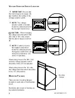
 Ensure that the voltage selector switch is in the proper position for 

the required supply voltage prior to connecting the unit to the power sup-

ply.

Locate the voltage selector switch inside the exhaust panel on the top 

1. 

right hand corner of the unit.

Flip the switch from 240 volt to 120 volt configuration. (230 and 115 is 

2. 

printed on switch)

Loosen the screw securing the junction box cover and remove the cover.

3. 

Remove the knockouts (if necessary) or use the provided cable clamp.

4. 

Pull out the four wires marked L1, L2, N, and G.

5. 

Connect the black L1 wire from the unit to the black L1 from the power 

6. 

supply.

Connect the red L2 and white N wire from the unit to the white neutral wire 

7. 

from the power supply.

Connect the green ground wire from the unit to the ground from the power 

8. 

supply.

When the unit has been configured for the appropriate power supply volt-

9. 

age, ensure that all connections are tight.  

Insert all the wiring back into the unit and secure with a cable clamp.

10. 


FIREPLACE JUNCTION bOX


120 v 

POWER 

SUPPLY 

(bREAKER 

PANEL) 


WHITE WIRE -


N


RED WIRE 


L2 

BLACK WIRE 

– L1 

WHITE WIRE -


N


BLACK WIRE 

– L1 

GROUND WIRE -


G


GREEN WIRE - G

www.dimplex.com

Summary of Contents for BFSL33

Page 1: ...irst before attempting to install or use this fireplace For your safety always comply with all warnings and safety instructions contained in this manual to prevent personal injury or property damage T...

Page 2: ...Power Wall Switch Wiring 10 Wiring For 240 Volt 10 Wiring For 120 Volt 12 Wiring For 120 Volt No Heat Installation 14 Section E 16 Heater Wall Switch Wiring For 120 240 Volt 16 Wall Mounting Thermost...

Page 3: ...connecting power supply wire to junction box on fireplace when installing after finishing wall Remove the outer jacket and strip the individual conductors from the end Loosen the screw securing the j...

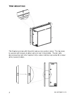
Page 4: ...three trim pieces top and two sides The top piece is secured with screws at either end and one in the middle The two side pieces require a tab to be inserted in the center slot then secured with a sc...

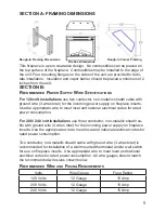
Page 5: ...Use the appropriate wire to meet local and national electrical codes for rated power consumption For 208 240 volt installations use three conductor non metallic sheath ca ble with ground wire 4 wires...

Page 6: ...sert a flat headed screwdriver inside the exhaust panel to change the switch from 240 volts 230 position to 120 volts 115 position When wiring the unit for 208 240 volts the voltage selector switch sh...

Page 7: ...volt position 230 is printed on 2 switch Loosen the screw securing the junction box cover and remove the cover 3 Remove the knockouts if necessary or use the provided cable clamp 4 Pull out the four w...

Page 8: ...5 is 2 printed on switch Loosen the screw securing the junction box cover and remove the cover 3 Remove the knockouts if necessary or use the provided cable clamp 4 Pull out the four wires marked L1 L...

Page 9: ...nted on switch Loosen the screw securing the junction box cover and remove the cover 3 Remove the knockouts if necessary or use the provided cable clamp 4 Pull out the four wires marked L1 L2 N and G...

Page 10: ...7 the L1 terminal of the main power wall switch Connect the red L2 wire from the unit to the red L2 wire from the main 8 power wall switch by using a wire connector not supplied Connect the other end...

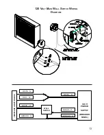
Page 11: ...11 240 Volt Main Wall Switch Wiring Diagram FIREPLACE JUNCTION bOX 240 v POWER SUPPLY bREAKER PANEL WHITE N RED L2 BLACK L1 WHITE N BLACK L1 GROUND G WALL SWITCh RED L2 GROUND G...

Page 12: ...1 wire from the 6 main power wall switch using a wire connector not supplied Connect the other end of the black L1 wire to the L1 terminal of the main 7 power wall switch Connect the red L2 wire from...

Page 13: ...13 120 Volt Main Wall Switch Wiring Diagram FIREPLACE JUNCTION bOX 120 v POWER SUPPLY bREAKER PANEL WHITE N RED L2 BLACK L1 WHITE N BLACK L1 GROUND G WALL SWITCh GROUND G...

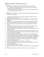
Page 14: ...main power wall switch using a wire connector not supplied Connect the other end of the black L1 wire to the L1 terminal of the main 7 power wall switch Connect the red L2 wire from the unit and the...

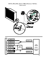
Page 15: ...Volt Main Wall Switch Wiring Diagram No Heat Installation FIREPLACE JUNCTION bOX 120 v POWER SUPPLY bREAKER PANEL WHITE N RED L2 BLACK L1 WHITE N BLACK L1 GROUND G WALL SWITCh GROUND G RED 1 RED 2 WIR...

Page 16: ...the black L1 wire from the 5 heater wall switch by using a wire connector not supplied Connect the other end of black L1 wire from the heater wall switch to the 6 L1 terminal of the heater wall switch...

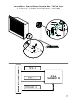
Page 17: ...17 Heater Wall Switch Wiring Diagram For 120 240 Volt See Section C or Section D For Main Power Connection FIREPLACE JUNCTION bOX WALL ThERMOSTAT RED 1 GROUND G RED 2...

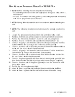
Page 18: ...nect the red 1 wire from the unit to the white neutral wire from the 5 wall thermostat box by using a wire connector not supplied Connect the other end of the white neutral wire from the thermostat wa...

Page 19: ...19 Wall Mounted Thermostat Wiring Diagram For 120 240 Volt See Section C or Section D For Main Power Connection FIREPLACE JUNCTION bOX WALL ThERMOSTAT RED 1 GROUND G RED 2...

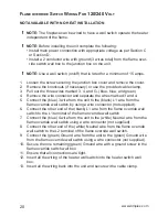
Page 20: ...the blue 3 wire from the unit to the black L1 wire from the 5 flame override wall switch by using a wire connector not supplied Connect the other end of the black L1 wire from the flame override wall...

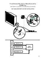
Page 21: ...me Override Wall Switch Wiring Diagram For 120 240 Volt See Section C or Section D For Main Power Connection NOT AVAILABLE WITH NO HEAT INSTALLATION FIREPLACE JUNCTION bOX BLUE 4 WALL SWITCh BLUE 3 GR...

Page 22: ...OR D D LED DRIVER BOARD LED PCB BOARD BLACK AC L WHITE AC N RED DC YELLOW DC SPECIAL NOTE ON LED BOARD CONNECTION BOTH AC AND DC POLARITIES MUST BE CONNECTED AS SHOWN TO MAKE LED WORK F F T T LOGSET D...

Reviews: