background image

13

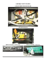
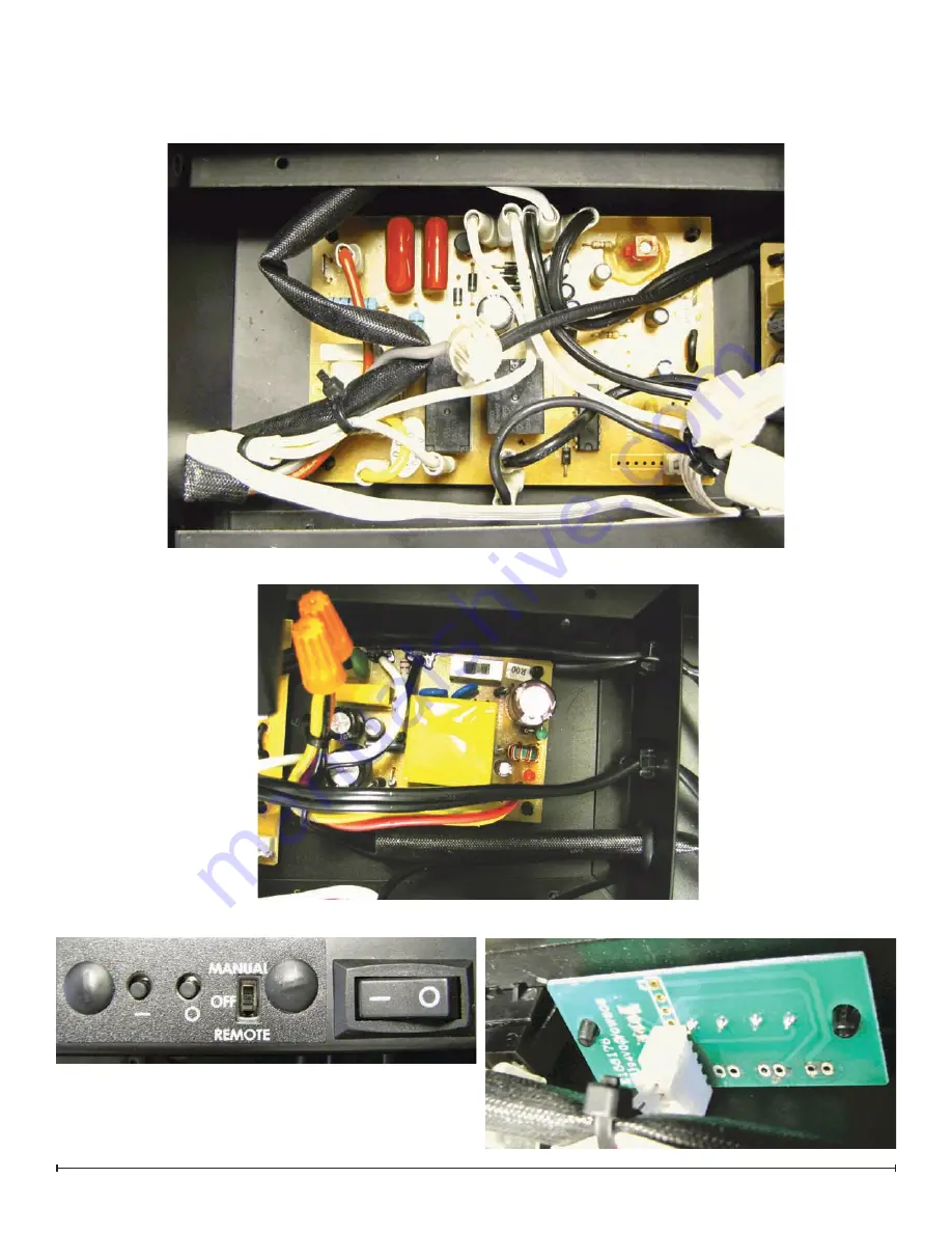
3-STAgE REMOTE RECEIVER BOARD

LED DRIVER BOARD

SWITCH HOUSINg - Outside View

SWITCH HOUSINg - Inside View

ASSEMBLY PART PICTURES

Summary of Contents for BLF50

Page 1: ...America Limited Dimplex North America Limited 1367 Industrial Road Cambridge ON Canada N1R 7G8 1 888 346 7539 www dimplex com REV PCN DATE 00 21 JUL 11 IMPORTANT SAFETY INFORMATION Always read this m...

Page 2: ...s injury or death OPERATION 3 Exploded Parts Diagram 4 Wiring Diagram 5 PREPARATION FOR SERVICE 6 INSTRUCTIONS FOR REMOVING FROM WALL 7 Surface Mount 7 Recessed Mount Partial In wall 8 Flush Mount Com...

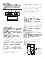
Page 3: ...mitter 1 Figure 2 Install one 1 12 Volt A23 battery in the battery 2 holder Close the battery cover 3 Battery must be recycled or disposed of properly Check with your Local Authority or Retailer for r...

Page 4: ...lass 5901930100RP Power Cord 8400320100RP Flicker Motor 2000220100RP Flicker Assembly 5901910100RP Cutout 2300200100RP LED Strips 3000830100RP Remote Receiver 3000820100RP Switch Board 3000820200RP LE...

Page 5: ...5 Wiring Diagram LED DISPLAY BOARD LED DRIVER BOARD CAPACITOR TERMINAL BLOCK FLICKER MOTOR SWITCH BOARD 3 STAGE RECEIVER BOARD LINEAR SWITCH ON OFF CORD BLOWER CUT OUT ELEMENT WIRE NUT WIRE NUT...

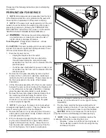
Page 6: ...y off of the 4 mounts located 3 between the outer and inner casing of the fireplace 2 on the left and 2 on the right FIGURE 4 Carefully place the glass assembly aside in a safe location Remove the dec...

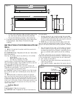
Page 7: ...nt of the cover Lift the cover off and set aside Disconnect the 2 wire connectors connected to the power source taking note of their original configuration Surface Mount FIGURE 7 Tools Required Philip...

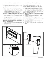
Page 8: ...ng to the 4 repair being performed Once repair is complete reassemble in the reverse order as 5 above Flush Mount Complete In wall FIGURE 10 Tools Required Philips head screwdriver various lengths CAU...

Page 9: ...the light covers and re attach the 12 covers with the screws from the outer bottom panel of the fireplace Reconnect the wires at the LED Driver board at the top 13 using the 2 orange wire connectors f...

Page 10: ...nected to this piece so carefully move it farther down in the body of the unit to give some room to access the heater assembly housing Release the top panel of the heater assembly hous 4 ing by removi...

Page 11: ...w the manual control switches on the top right Remove cover and set aside Remove the panel that spans across the top front facia 2 To do so locate 4 screws 2 on the left and 2 right on the angled part...

Page 12: ...he reverse order as above 6 POWER CORD REPLACEMENT Tools required Phillips head screw driver Needle nosed pliers CAUTION Follow Preparation for Service instructions before proceeding CAUTION Follow In...

Page 13: ...13 3 STAGE REMOTE RECEIVER BOARD LED DRIVER BOARD SWITCH HOUSING Outside View SWITCH HOUSING Inside View ASSEMBLY PART PICTURES...

Page 14: ...14 www dimplex com LOWER ELECTRICAL HOUSING With Housing Cover and Flicker Rod in place LOWER ELECTRICAL HOUSING With Housing Cover and Flicker Rod Removed LED LIGHT STRIPS...

Page 15: ...15 LED LIGHT STRIP WIRE HARNESS HEATER ASSEMBLY ELEMENT CONNECTIONS Left and Right Side...

Page 16: ...16 www dimplex com HIGH TEMPERATURE CUTOUT Below Element Housing BLOWER MOTOR CONNECTIONS Below Element Housing...

Reviews: