background image

9

6.  Install the new cord.

7.  Reassemble in the reverse order as above. 

Light Assembly Replacement

Tools Required:

  Philips head screwdriver

Flat Head Screwdriver

  WARNING:

  Disconnect power before attempting any 

maintenance to reduce the risk of electric shock or damage 
to persons.

!

 NOTE: 

Ensure that all of the components that 

contain water have been emptied before performing any 
maintenance.

1.  Disconnect and remove the media from the unit and 

put them in a safe place.

2. 

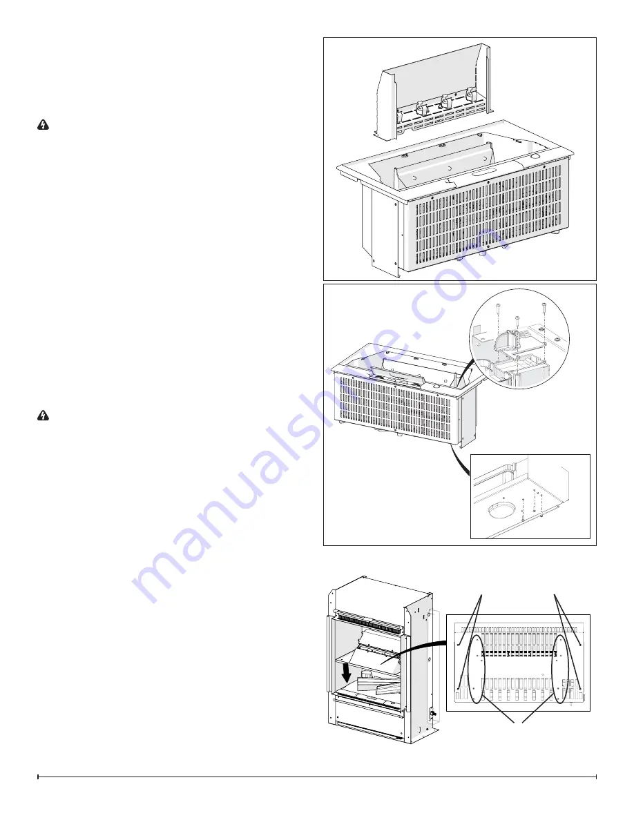
Disassemble the sump components. (Figure 3)

3.  With the unit turned upside down, remove the 2 screws 

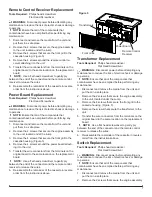
that hold the light assembly to the unit. (Figure 6)

4.  Remove the light assembly and replace with the new 

light assembly. 

5.  Reattach the wire onto the new light assembly.

6.  Re-assemble the remainder of the cassette in reverse 

order from the instructions above.

Fan Motor and Fan Housing 
Replacement

Tools Required:

  Philips head screwdriver

Flat Head Screwdriver

  WARNING:

  Disconnect power before attempting any 

maintenance to reduce the risk of electric shock or damage 
to persons.

!

 NOTE: 

Ensure that all of the components that 

contain water have been emptied before performing any 
maintenance.

1.  Disconnect and remove the media from the unit and 

put them in a safe place.

2. 

Disassemble the sump components. (Figure 3)

3.  Remove the 2 screws that secure the engine assembly 

to the unit, located under the sump.

4.  Remove the 3 screws that hold the cover onto the fan 

housing. (Figure 7)

5.  Remove the fan motor out of the housing and discon-

nect the wiring connection located near the bottom of 
the housing.

6.  If replacing only the motor, attach new motor and reas-

semble the remainder of the cassette in revers order 
from the instructions above.

• 

If replacing the housing, remove the 3 screws attaching 

the base to the cassette. (Figure 7)

7.  Attach new fan housing base to the cassette.

8. 

Transfer the filter from the old housing to the new hous

-

ing.

9.  Reinstall the fan motor and reconnect the wire.

10.  Re-assemble the remainder of the cassette in reverse 

Figure 6

Figure 7

Figure 8

Heater Assembly 

Attachment Screws

Support Plate  
Attachment Screws

Summary of Contents for BOF4056

Page 1: ...tice 2014 Dimplex North America Limited Dimplex North America Limited 1367 Industrial Road Cambridge ON Canada N1R 7G8 1 888 346 7539 www dimplex com REV PCN DATE 00 7 MAY 14 IMPORTANT SAFETY INFORMAT...

Page 2: ...niques which if not carefully followed will expose the user to the risk of fire serious injury or death Operation 3 Maintenance 4 Exploded Parts Diagram 5 Replacement Parts 5 Wiring Diagram 6 Remote C...

Page 3: ...cycling advice in your area Operation NOTE When the engine is used in an environment where background noise is very low it may be possible to hear a sound which is related to the operation of the flam...

Page 4: ...AUTION Allow at least twenty minutes for light bulbs to cool before touching bulbs to avoid accidental burning of skin 1 Leaving the flame effect on remove the rock media tray and water tank and lift...

Page 5: ...Container 0441440300RP 8 Top Cover Assembly 9600670100RP 9 Water Reservoir Sump 0441380100RP 10 Fan Assembly 5300300100RP 11 Fan Housing Assembly 9600540100RP 12 Fan Filter 8600300100RP 13 Transducer...

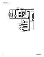
Page 6: ...6 www dimplex com Wiring Diagram...

Page 7: ...the unit 5 Transfer the wire connectors from the terminals on the original board to the same location on the replacement board NOTE Use a flat head screwdriver to gently pry between the end of the co...

Page 8: ...iometer Replacement Tools Required Philips head screwdriver Flat Head Screwdriver 3 8 10mm Wrench WARNING Disconnect power before attempting any maintenance to reduce the risk of electric shock or dam...

Page 9: ...r before attempting any maintenance to reduce the risk of electric shock or damage to persons NOTE Ensure that all of the components that contain water have been emptied before performing any maintena...

Page 10: ...intenance 1 Remove the 10 screws that attach the heater assembly to the support plate Figure 8 1 Remove the 4 screws securing the heater support plate to the unit Figure 8 2 Gently drop the support pl...

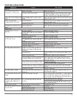
Page 11: ...ch A is in the ON I position but mode Switch B has not been pressed Figure 2 Press Switch B once for flame effect Figure 2 Low water level Check the water tank is full and there is water in the sump W...

Page 12: ...the heater is initially turned on The heater is burning off any dust accumulated during manufacturing or operation Defective heater assembly Replace heater assembly Heater fan turns on but heater lack...

Reviews: