2
General Information
Installation Instructions
This section describes how to install and set up your fire.
Before you start:
Ensure that all packing items are removed (read any warning labels carefully) and retain all packing for possible future
use.
Before connecting the appliance, check that the supply voltage is the same as that stated on the appliance.
CONNECTIONS REQUIRED IN ADVANCE OF INSTALLATION
Electrical Connection
Please ensure a 230V / 16A power socket is located within 1m of the product. The electrical connection should be
accessible during product installation so that the connection can be made to the product easily.
BUILDING THE PRODUCT SURROUND/ENCLOSURE
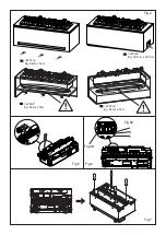
This product can be built into a wall, surround or structure. Please take note of the product dimensions (Fig.1) and build
your wall, surround or structure accordingly. Suitable clearance should be provided to allow the product to be installed
easily.
You are required to leave a minimum of 400mm from the base of the fuel bed to any shelf/enclosure above the product
(Fig. 2). This will allow enough space above the product to allow the flame effect to form fully and not to be obstructed.
When determining a location for the product, ensure that the unit will not be susceptible to drafts, vents, ceiling fans and
other air currents. Similar to a candle, large movements of air will affect the unit’s ability to create and maintain the flame
effect. If the desired location is susceptible to significant air movement, i.e. air vents, the different installation options
illustrated in Fig 2 can be used.
VENTILATION
This product needs free ventilation from underneath to operate correctly. There are slots on the underside of the product
to allow this free air through the product. The free ventilation helps keep the electronic components cool and allows the
mist to rise and leave the product. Please see Fig 3 & 4 for examples of the required ventilation. Please take note of the
requirement for a ventilation opening on the shelf where the product sits, to allow a clear path for the air to get to the
product.
CAS500R Free Ventilation Area: Minimum 210cm
2
CAS1000R Free Ventilation Area: Minimum 420cm
2
ELECTRICAL CONNECTION
Plug the fire into a 16amp/230 Volt outlet. Be sure to have access to the plug after installation to allow for disconnection.
Ensure that the supply cable exits at the back of the fire at the right or left hand corner to suit your supply socket location
and is not trapped under the fire such that it might cause it to be damaged.
The appliance can be connected to the fixed wiring of the premises through a suitable connection box positioned
adjacent to the appliance. This electrical installation must be carried out by a competent electrician and be in strict
Only use filtered/decalcified water in this appliance.
Unpack the appliance carefully and retain the packaging for possible future use, in the event of moving or returning
the fire to your supplier.
Always ensure that the appliance is sitting on a level surface.
The appliance is a flame effect only.
The appliance is designed to be built into a surround or built into a wall.
Please note: Used in an environment where background noise is very low, it may be possible to hear a sound which is
related to the operation of the flame effect. This is normal and should not be a cause for concern.
Once installed, never move this appliance or lay on its back, without draining the water from sump and water tank.
The water tank, sump, sump lid, tank cap and air filters must be cleaned once every 2 weeks, particularly in hard
water areas.
If you intend not using the appliance for longer than 2 weeks, drain the water from sump and water tank and dry the
sump.
The sump and the water tank in this product are treated with a biocidal product, Silver Biocide. This conforms to the
latest relevant ISO standard
s this product contains and utilises water as an aspect of its operation, the adherence to the cleaning requirement as
detailed within the instructions is necessary to ensure that risk/s through bacterial proliferation are minimised. It is ad-
ditionally recommended that if this unit is connected to a water supply, that it becomes included within any Legionella
assessment. Please refer to the Maintenance section in the following instruction booklet for details on the cleaning
Do not drink the water from the sump or from the water tank(s).
Summary of Contents for CAS1000R
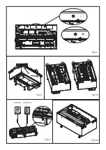
Page 12: ...Fig 10 Fig 8 Fig 9 Fig 11 Fig 12A CAS500R CAS1000R...
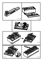
Page 13: ...Fig 13 Fig 12B Fig 14 Fig 15 Fig 16 Fig 17...
Page 14: ...Fig 18 Fig 19 Fig 20 Fig 19A Fig 19B...
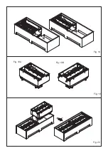
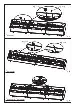
Page 15: ...Fig 21A Fig 21B Fig 21 Fig 23 CAS500R CAS500R CAS1000R CAS1000R Fig 22 Fig 22A Fig 22B...
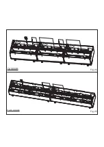
Page 16: ...Fig 24 CAS500R Fig 25 CAS1000R...
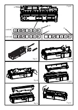
Page 17: ...Fig 26 Fig 27 Fig 29 CAS1000 CAS500 A Fig 30 B C D Fig 28 Fig 31 Fig 32...
Page 18: ......
Page 19: ......


