3
accordance with the current I.E.E regulations for Electrical Equipment in Buildings.
The electrician can remove the supplied plug by the following;
1. Lift off the fuelbed and put switch ‘A’ into the off position (Fig 26).
2. Ensure that the appliance is unplugged.
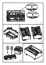
3. Lift off the access cover by removing the retaining screw (Fig 5).
4. Unscrew and remove the Live, Neutral and Earth wires (Fig 6A)
5. Unscrew the cable clamp (Fig 6B) and remove the supply cord.
6. The electrician can then connect the wire from the appliance to the connection box (by following the steps above in
reverse) ensuring that it incorporates a double pole isolating switch, having a contact separation of at least 3mm.
Brown - Live (L), Blue - Neutral (N) and Green/Yellow - Earth (E)
INSTALLING THE PRODUCT INTO SURROUND/ENCLOSURE
Once your enclosure has been built to the required dimensions and the electrical connection has been installed, follow
the steps below to install your product.
1. Sit the product on the constructed base, ensuring the cable is accessible and not caught under the product.
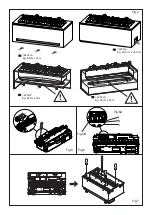
2. Ensure the product is at the correct height to suit the installation and ensure it is adequately level. This can be done
by adjusting the adjustable feet with a flat head screwdriver. (Fig 7) The levelness of the product can be verified by
checking the on-board spirit level which is located on the metal base towards the back of the fire (Fig 8).
3. Once the product is at the correct height and is level, centre the product within the opening. If using the LED log fuel
bed (which is wider than the product), this can be done by fitting the fuel bed to the product. The fuel bed will centre
itself within the opening and its guides will centre the product underneath (Fig 9).
4.
With the product in its final position, remove the fuel bed and screw the product to the surround using the four fixing
holes shown in Fig 10.
COMMISSIONING/INITIAL PRODUCT START-UP
Connecting the Receiver/Tethered Remote
With the fuel bed removed, insert the 3.5mm jack of the Bluetooth receiver into the socket at the back of the appliance
(Fig 11). It is important to ensure that the jack is pushed fully into the socket. Failure to fully insert the jack will prevent
the product from functioning correctly. The receiver has a cable length of 1.4m which will allow you position it anywhere
around the product. If you prefer to hide it, the receiver can be placed inside the surround/wall. Please ensure that the
receiver is not enclosed in metal, concrete or any other dense material, this will affect the signal from the remote control.
Filling the Water Tank
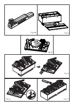
Before powering on the product for the first time, ensure that a full water tank has been placed on the product. Remove
the water tank from its location on top of the sump (Fig 12A) and open it by unscrewing the orange cap (Fig 12B). The
tank should be filled with filtered/decalcified water only. When the tank is replaced on top of the sump, it will take about
one minute for the tank to empty into the sump. Allow the sump to fill fully before switching on the product. Once filling
is complete, the tank can be refilled and replaced on top of the sump. This will allow for the maximum capacity of water
to be stored in the product.
Installing the Log Fuel Bed (If Supplied)
The product is supplied with a ‘metal fuel bed’ fitted. If you have chosen to operate your product with a log fuel bed,
remove this metal fuel bed and retain it for future use (Fig. 13). Follow the steps below to install the log fuel bed.
1.
Gently lift the LED Log fuel bed out of its packaging. CAUTION: The fuel bed weighs 5kg. Be sure to only lift the fuel
bed by the two centre logs (Fig. 14).
2. Place the fuel bed on top of the appliance, there are 4 plastic guides under the fuel bed to help locate it (Fig.9).
Please note the fuel bed can be placed front to back or back to front on the product.
3. Once the fuel bed is in place, remove the small loose log (Fig 15). This small log is secured with magnets and should
easily lift off the fuel bed.
4.
Locate the DC jack under the small log and connect it to the corresponding DC jack located on the product through
the hole in the fuel bed (Fig.16).
5. Each log fuel bed is supplied with a loose non LED log. For single CAS500R installations, this can be placed on top
of the fuel bed or stored away with the packaging. For CAS1000R or multiple product installations, the loose log can
be placed on the join in the centre between two fuel beds (Fig 17).
MULTIPLE PRODUCT INSTALLATION (DAISY CHAINING)
Power Connections
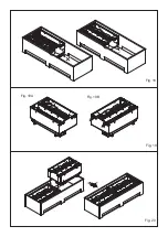
Both the CAS500R and CAS1000R products can be installed side by side to elongate the flame effect. When supplying
power to multiple products, ensure the maximum wattage of the combined products does not exceed the rated capacity
of the MCB (Minature Circuit Breaker) in the circuit.
Multiple Product Installation
Follow steps 1-4 in “Installing the Product into Surround/Enclosure” to fit the first product. It is important that the first
Summary of Contents for CAS1000R
Page 12: ...Fig 10 Fig 8 Fig 9 Fig 11 Fig 12A CAS500R CAS1000R...
Page 13: ...Fig 13 Fig 12B Fig 14 Fig 15 Fig 16 Fig 17...
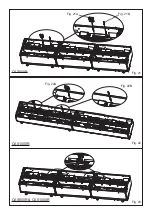
Page 14: ...Fig 18 Fig 19 Fig 20 Fig 19A Fig 19B...
Page 15: ...Fig 21A Fig 21B Fig 21 Fig 23 CAS500R CAS500R CAS1000R CAS1000R Fig 22 Fig 22A Fig 22B...
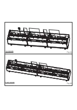
Page 16: ...Fig 24 CAS500R Fig 25 CAS1000R...
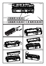
Page 17: ...Fig 26 Fig 27 Fig 29 CAS1000 CAS500 A Fig 30 B C D Fig 28 Fig 31 Fig 32...
Page 18: ......
Page 19: ......


