7
AFTER SALES SERVICE
Your product is guaranteed for two years from the date of purchase. Within this period, we undertake to repair or
exchange this product free of charge (excluding transducer discs & subject to availability) provided it has been installed
and operated in accordance with these instructions. Your rights under this guarantee are additional to your statutory
rights, which in turn are not affected by this guarantee.
RECYCLING
For electrical products sold within the European Community - At the end of the electrical products useful life
it not be disposed of with household waste. Please recycle where facilities exist. Check with your Local
Authority or retailer for recycling advice in your country.
PATENT / PATENT APPLICATION
Products within the Optimyst range are protected by one or more of the following patents and patent applications:
Great Britain GB2460259B, GB2475794B, GB2418014, EP2029941, GB2436212, GB2402206B
United States US8413358, US8136276, US7967690, US8574086
Russia RU2434181
European EP2029941, EP2315976, EP1787063 (A1), EP2388527, EP2029941,
China CN101883953A, CN102105746A, CN101057105 (A), CN101438104
Australia AU2009248743A1, AU2007224634
Canada CA2725214, CA2579444, CA2645939
South Africa ZA2008/08702
Mexico MX2008011712
South Korea KR101364191
Japan JP5281417, JP5496291
Brazil BRP10708894
India 4122/KOLNP/2008
New Zealand NZ571900
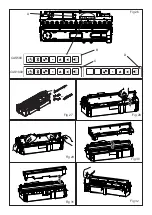
4. Disconnect the electrical connector to the transducers, located on the right side of the sump. (Fig 28).
5. There are two orange clips holding down the nozzle on the sump; one on the left and one on the right hand side of
the nozzle. On the left side, press in the clip with one hand and with the other lift the nozzle out of the clip. Repeat
this for the right side (Fig 29). The nozzle can now be lifted up and placed aside (Fig 30).
6. Gently lift up the sump (Fig 31), taking care to keep it level so as not to spill any water. Sit the sump in the sink.
7. Carefully empty the sump into the sink taking note that the transducer is held in place by a retaining clip.
8. Put a small amount of washing up liquid into the sump, and using a soft brush, gently clean all surfaces in the sump
and gently clean the transducer including the cone and metal discs located in the top grooved surface.
9. When cleaned, thoroughly rinse the sump with clean water to remove all traces of washing up liquid.
10.
Clean the nozzle with a soft brush and flush out thoroughly with water.
11. Reverse the above steps 1 – 6 to reassemble.
Transducer
The transducer is a consumable item and may need to be replaced through time, depending on its usage. Replacement
transducers can be purchased from our your dealer. The transducer is fixed in the sump with a plastic clip. If you need
to replace your transducer:
1. Follow the steps 1-5 in the CLEANING - Sump section under ‘Maintenance’ to gain access to the transducer.
2. Press the clip back and lift the transducer upwards out of its holder.
3. Place the new transducer into the sump, ensuring the its cable does not sit over the cone.
4. Reverse the above steps to reassemble the nozzle and sump.
Air Filter
1. Gently lift out the fuel bed and place it aside.
2.
Gently slide the air filter upwards out of its plastic holder. (Fig 32)
3. Gently rinse with water in the sink and dry with fabric towel.
4.
Replace the filter making sure that the coarse black filter is facing outwards.
5. Replace the fuel bed.
Additional Information
Summary of Contents for CAS1000R
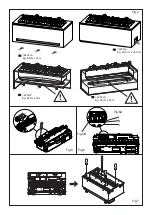
Page 12: ...Fig 10 Fig 8 Fig 9 Fig 11 Fig 12A CAS500R CAS1000R...
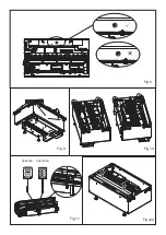
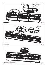
Page 13: ...Fig 13 Fig 12B Fig 14 Fig 15 Fig 16 Fig 17...
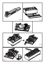
Page 14: ...Fig 18 Fig 19 Fig 20 Fig 19A Fig 19B...
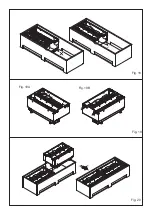
Page 15: ...Fig 21A Fig 21B Fig 21 Fig 23 CAS500R CAS500R CAS1000R CAS1000R Fig 22 Fig 22A Fig 22B...
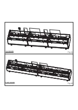
Page 16: ...Fig 24 CAS500R Fig 25 CAS1000R...
Page 17: ...Fig 26 Fig 27 Fig 29 CAS1000 CAS500 A Fig 30 B C D Fig 28 Fig 31 Fig 32...
Page 18: ......
Page 19: ......


