3
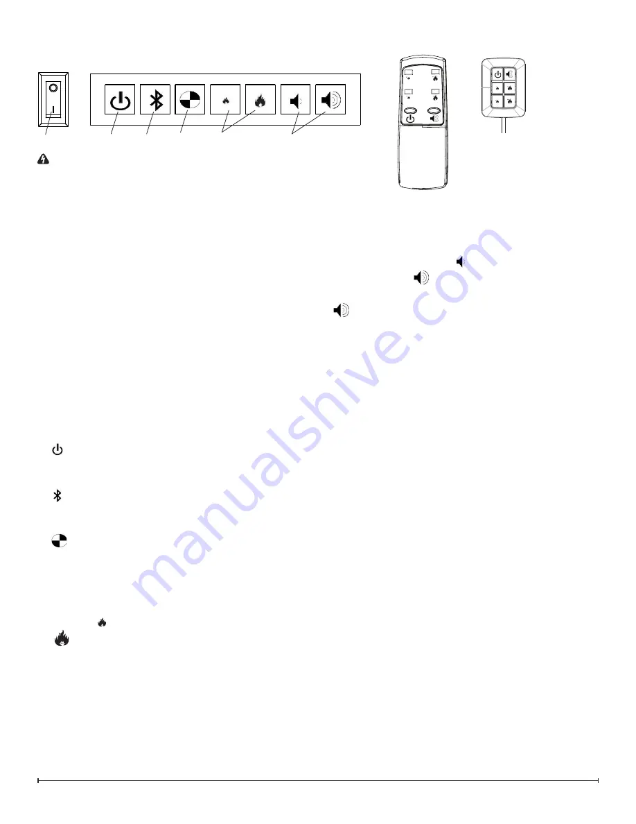
F . Volume Control
Adjusts the volume of the wood fire sound effects.
On the unit
: Pressing the will decrease the volume
and pressing the
will increase the volume.
On the Remote and Tethered Controller
: Pressing the
will turn On and Off the volume.
Remote Control
The tethered controller can be used in the same manner as
the remote but houses the blue tooth receiver for communi-
cation with the remote.
The tethered controller must be connected to the unit and
On/Off Switch must be in the ‘ON’
( I )
position in order for
the remote to operate.
!
NOTE:
To operate correctly the remote control must be
initialized with the unit.
Remote Control Initialization/ Reprogram
In order for the remote to communicate with the unit the
blue tooth must be setup, as outlined below:
1. Install the tethered controller to the unit - plug into the
port on the on the right module and run the wire out of
the housing through the opening in the center of the
back panel.
2. Place the On/Off Switch (Figure 1A) in the On (“I”) posi-
tion.
3. Press the blue tooth initialization button on the Primary
controls (left side).
4. The unit will begin to beep and turn the lights on and off
every 2 ½ seconds to indicate that the unit is in syn-
chronization mode.
5. Within 20 seconds of pressing the blue tooth button,
press any button on the remote control (Figure 2).
!
NOTE:
You will have only 20 seconds to perform this
last step. Failure to do so will result in these steps needing
to be followed again.
6. If the synchronization was successful the unit will go to
Standby.
This will synchronize the remote control and the fireplace
receiver.
OPERATION
Figure 1
WARNING:
This electric firebox must be properly in-
stalled before it is used.
The unit has two separate internal modules that are con-
trolled by the settings entered on the left side (primary).
Finer adjustment can be done using the controls on the
right module to have both modules operating at the same
level (secondary).
There are three different control options available for the
unit: manual (under the media tray), tethered controller
(must be connected to the unit) and a remote control.
!
NOTE:
When the unit is used in an environment where
background noise is very low, it may be possible to hear a
sound which is related to the operation of the flame effect.
This is normal and should not be a cause for concern.
!
NOTE:
Always ensure that the appliance is fixed to the
framing in a level position.
Controls
A . On/Off Switch
Supplies power to the unit.
!
NOTE:
When the unit is first turned on the lights will
come on and mist will appear 45 seconds later.
B . Standby
Puts the unit into standby mode where control by the teth-
ered controller or remote is possible.
C . Blue tooth
Required for initializing the remote together, see initializa-
tion instructions for more detail.
D .
Test Mode
Used for troubleshooting issues - outlined in detail in the
service manual.
E . Flame Intensity Control
Adjusts the intensity of the flame and smoke effect when
the unit has been activated.
Pressing the
will decrease the flame effect and pressing
the
will increase the flame effect.
!
NOTE:
A few moments will be required between adjust-
ment and a change to the flame effect.
!
NOTE:
During normal operation it is expected to see
some condensation of water on the media tray. This will
vary depending on ambient conditions and should be con-
sidered normal.
!
NOTE:
When the water tank is empty the unit will turn
off after 30 seconds.
Figure 2
B
A
C
D
E
F
Remote
Control
Tethered
Controller
!
NOTE:
The icons
with 1 dot indicate con-
trols for the primary and
2 dots indicate controls
for the secondary.

