background image


www.dimplex.com

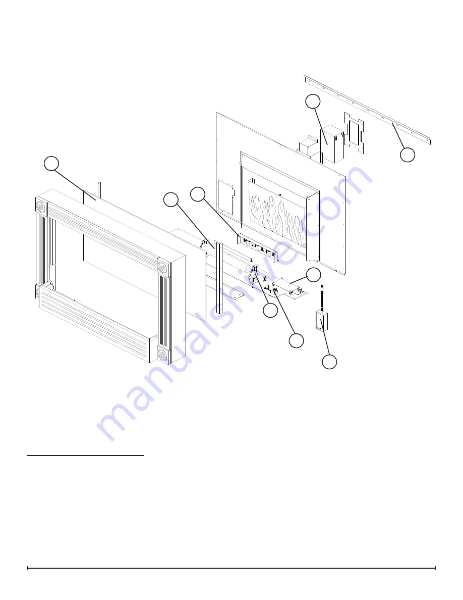
ExPLODED PARTS DIAgRAM

Replacement Parts List

6

1

2

3

4

10

8

5

Flicker Motor

1. 

 . . . . . . . . . . . . . . . . . . . . .3000240200KIT

Flicker Rod

2. 

 . . . . . . . . . . . . . . . . . . . . . . 5901590100RP

Battery, 12V, 8Ah, .25” terminals

3. 

 . . . . . . 3700150100RP

Switch, ON/OFF Momentary SPDT

4. 

 . . . 2800220100RP

PCB; Driver Board; Charger; DC Jack

5. 

 . 3000750100RP

AC/DC Power Supply with cord

6. 

 . . . . . . 3700180100RP

Partially Reflective Glass Assembly 

7. 

 . . . 5901550100RP

LED Light Assembly

8. 

 . . . . . . . . . . . . . . . 6908300100RP

Battery Wire Harness

9. 

 . . . . . . . . . . . . . . 2500560100RP

Wall Mounting Bracket 

10. 

 . . . . . . . . . . . . . 1021650100RP

River Rocks, Large

11. 

 . . . . . . . . . . . . . . . . 1400060100RP

7

Summary of Contents for CFA36BS

Page 1: ...plex North America Limited Dimplex North America Limited 1367 Industrial Road Cambridge ON Canada N1R 7G8 1 888 346 7539 www dimplex com REV PCN DATE 00 3 OCT 11 IMPORTANT SAFETY INFORMATION Always re...

Page 2: ...lly followed will result in damage to the equipment Warning Procedures and techniques which if not carefully followed will expose the user to the risk of fire serious injury or death OPERATION 3 Maint...

Page 3: ...t scratching do not use abrasive cleaners Fireplace Surface Cleaning Use only a damp cloth to clean painted surfaces of the fireplace Do not use abrasive cleaners Servicing Except for battery replacem...

Page 4: ...terminals 3 3700150100RP Switch ON OFF Momentary SPDT 4 2800220100RP PCB Driver Board Charger DC Jack 5 3000750100RP AC DC Power Supply with cord 6 3700180100RP Partially Reflective Glass Assembly 7...

Page 5: ...E LIGHT P N 3700140100 1 WATT LED FLAME LIGHT P N 3700140100 1 WATT LED FLAME LIGHT P N 3700140100 WIRE AND CONNECTORS PART OF PCB ON OFF SWITCH P N 2800220100 BATTERY CHARGER LED DRIVER CIRCUIT BOARD...

Page 6: ...om the wall 4 mounting bracket Figure 2 and carefully place it upright on a flat surface CAUTION A protective barrier i e blanket between the fireplace and work surface will help prevent scratches on...

Page 7: ...tery Figure 3 Once battery is out of the opening remove the two 2 8 wire lead connectors from the battery terminals taking note of their original configuration NOTE These wire connectors can be carefu...

Page 8: ...age the 2 wire con nections on the left side of the battery Figure 3 Once battery is out of the opening remove the two 2 8 wire lead connectors from the battery terminals taking note of their original...

Page 9: ...dle nosed pliers Set the Battery aside 9 Remove the remainder of the 17 screws which secure 10 the back panel on to the fireplace 3 along the top 3 along the right battery side 5 along the left switch...

Page 10: ...ing the original configura tion NOTE Pliers can be used for a better grip on the con nector or a flat head screw driver can be used to carefully pry up between the switch and connector if you are unab...

Page 11: ...nnections Dead Battery Replace Battery Defective LED PCB Replace LED PCB Flame Frozen Defective flicker motor Replace flicker motor Loose wiring Check wiring connections Flame not bright or flame not...

Reviews: