8
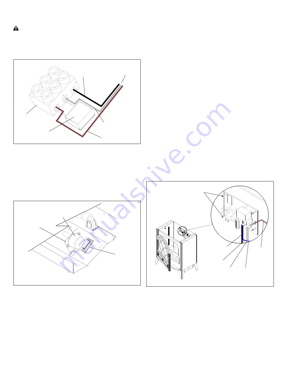
17. Connect the three (3) wires from the new motor to the
Terminal Block as they originally were (refer to Figure 8).
18. Follow steps 1 through 8 in reverse order to reassemble
the stove.
Remote Control Receiver Replacement
The Remote Control requires no replacement procedure
however, a reinitialization procedure may need to be
followed. Refer to Page 3 for the procedure.
If the stove was operating prior to servicing allow at least
10 minutes for light bulbs and heating element to cool off to
avoid accidental burning of skin.
Disconnect power before attempting any maintenance or
cleaning to reduce the risk of electric shock or damage to
persons.
Receiver Replacement Procedure:
1. Open stove door.
2. Remove the 11 Philips screws that attach the top panel to
the stove as shown in Figure 4 (page 6). There are: four
(4) screws along each side; and three (3) screws at the
front, accessible behind the door.
3. Remove top panel.
4. Slide partially reflective glass up from within the stove to
remove.
8. Remove four (4) Philips screws as shown in Figure 7 to
release the bottom pan.
CAUTION:
Use caution when removing the bottom pan
as the Heater Assembly is attached to it and is wired to
the stove.
9. On the underside of the stove interior, disconnect the
Figure 8
Terminal Block
Capacitor
Brown wire
White wire
Black wire
All wires lead to
Flicker Motor
three (3) wires from the Terminal Block that lead to the
Flicker Motor (Figure 8).
10. From inside the stove, pull the three (3) wires
disconnected in step 9 up through the stove (wires may
be encased in a sheath).
11. Remove the rubber sleeve from the Flicker Motor shaft.
12. Gently bend the Flicker Motor Bracket inwards enough
Figure 9
Shown exploded for clarity
Flicker
Motor
Flicker Motor
Bracket
Wires leading
to Terminal
Block
so that the two (2) screws that mount the motor to the
bracket are accessible (Figure 9).
13. Remove the Flicker Motor by removing the two (2) Philips
screws on either side of the motor.
14. Discard motor.
15. Properly orient replacement motor and attach to Flicker
Motor Bracket with screws removed in step 13.
16. Gently bend the Flicker Motor Bracket back into its
original position and feed the new motor’s wires through
the sheet metal to the Terminal Block.
Figure 10
Mounting
Studs (4)
Brown wire
to 3-Position
Switch
White wire to
base of stove
Grey wire to
heater switch
Blue wire to
thermostat
Black wire to
base of stove
5. The Remote Control Receiver is attached to the back
panel of the stove by four (4) mounting studs (Figure 10).
6. Disconnect all five (5) wire clips from the Remote Control
receiver, noting their original locations.
7. Depress the clasp of each mounting stud and release the
Remote Control receiver from the sheet metal.
8. Properly orient the replacement Remote Control receiver
and snap it into place on the four (4) Mounting Studs.
9. Using Figure 10 as a reference, reconnect the five (5)
Summary of Contents for CS33116A
Page 5: ...5 Wiring Diagram ...


